The user interface of visTABLE®touch
After starting visTABLE®touch from Windows®, first the license is checked. If you have a valid license for the program, the Start View is opened. From here, new or existing Layout Documents are opened in the User Interface for editing.
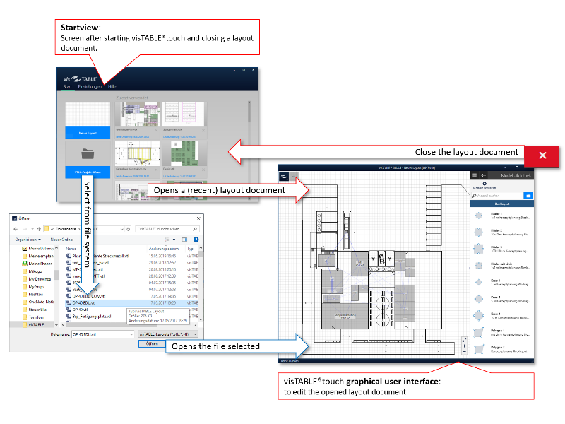
It is also possible to open layouts directly from Windows®. Double-clicking on a file linked with visTABLE®touch will skip the start view; the layout will then immediately be available for editing.
Structure of the user interface
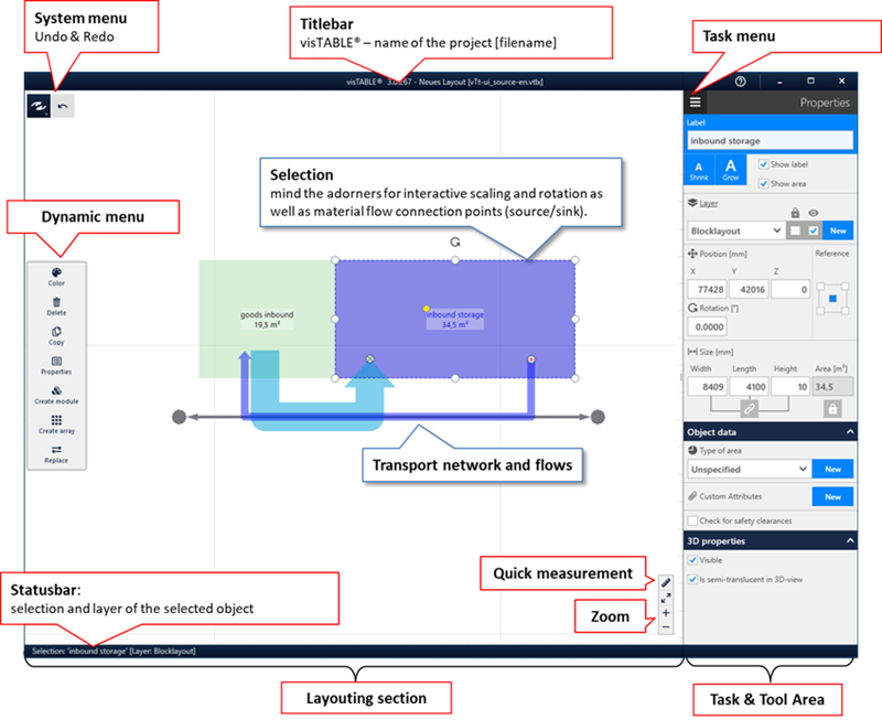
Title Bar: The number of the version of visTABLE®touch is displayed centrally on the left, the Project Name is specified after the hyphen, and the file name is put in square brackets. An asterisk (*) after the file name indicates that the Layout Document is not yet saved in the current state of editing.Layout Area: Working Area with Grid Lines for arranging the objects Comprises theSystem Menuand the buttons forUndo/Restore(top left), theDynamic Menu(on the left margin) and theZoomsection (bottom right).Task and Tool Area: Display area for the current task, includingTask MenuandTask Navigation.Status Bar: Indicates the identifier for the current selection and the corresponding layer. If the selection comprises several object groups, a corresponding text is output. Progress bars are displayed in the bottom right corner, e.g. during saving or comprehensive calculations.
The layout area
This is the working area of visTABLE®touch. In the layout area, objects of the Model Library are interactively arranged into Layouts by way of the mouse and/or finger gestures. When objects are selected, the Dynamic Menu is displayed which provides appropriate actions (e.g. copying, deletion, coloring) for selection. The selection is highlighted by means of selection markers (blue: one object; pink: several objects together); so-called adorners allow specific interactions.
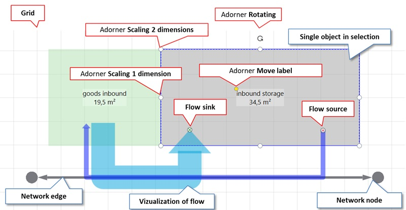
The following interactions are possible using the mouse or finger gestures:
- Select,
- Move (with/without object snapping),
- Rotate,
- Scaling,
- Move label,
- Quick measurement (quickly obtain the distance between two points in the layout),
- Zoom (enlarge/reduce visible layout area),
- Pan (move visible layout area).
Interactive selection
Selection is the general interaction for processing objects, i.e. only objects included in the selection (which is identified by highlighting) can be edited. Objects can be selected for the layout area either separately or together.
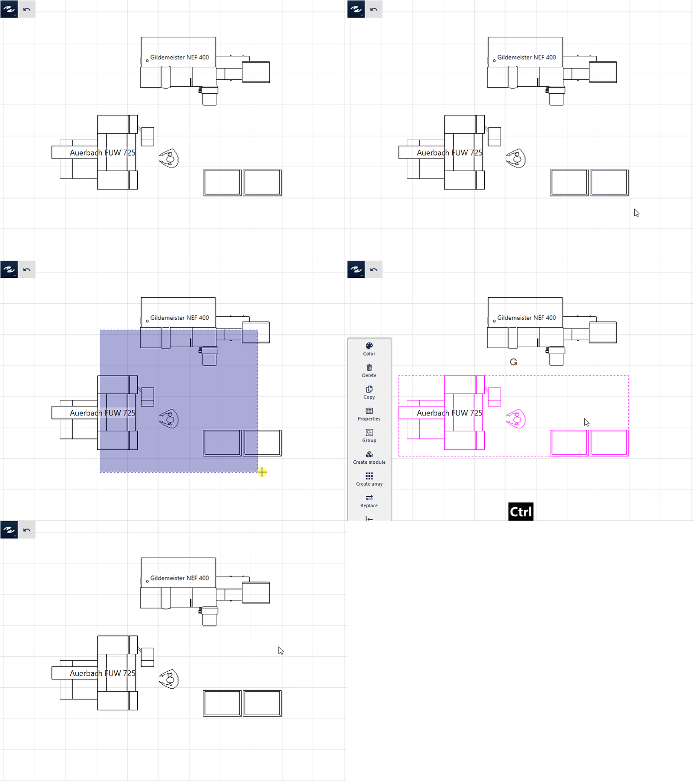
- The selection of single objects for the layout area is only possible for objects not arranged on locked or hidden layers. These objects are visible and are highlighted in color when you move the mouse over them. In this status, the objects can be selected by left-clicking or tapping. When the objects are selected successfully, they are highlighted in blue. To cancel or undo your selection, simply select another object, left-click or tap in a free layout area or press
<Esc>. - To add objects, click on the objects to be selected while simultaneously pressing and holding down the
<Ctrl>key. The result is a multiple selection with the selected objects highlighted in pink. - If objects are grouped, all objects of the group are indirectly included in the selection by way of the aforementioned interaction of selection. The result is also a multiple selection.
- Dragging will produce a selection rectangle. This will select all objects in the rectangle. The selection pertains to all objects that are touched or lie within the rectangle.
- Pressing and holding down the
<Ctrl>key and dragging will produce a selection rectangle. All objects touched by the selection rectangle are added to the current selection. If objects are touched by the rectangle which have already been selected, they will be deselected.
Selection
In addition to interactive selection, the Explorer/Search function is provided for structured object selection. Objects can indirectly pass in the selection if they are part of groups. It is also possible that objects pass in the selection on hidden or locked layers.
Interactive moving
- Capture the object to be moved near the geometry to be snapped to the target object. Then move the object towards the target object (object or near a grid line).
- Dragging moves the selected object in the desired direction.
- To finish moving, release the mouse button; the selected object will remain at the new target position.
Practical tip
Always select a zoom factor matching the targeting accuracy. For precise alignment, zoom in such that the targeted area fills the whole screen. For best results, use the middle mouse button and the mouse wheel.
Snapping objects to the grid when moving
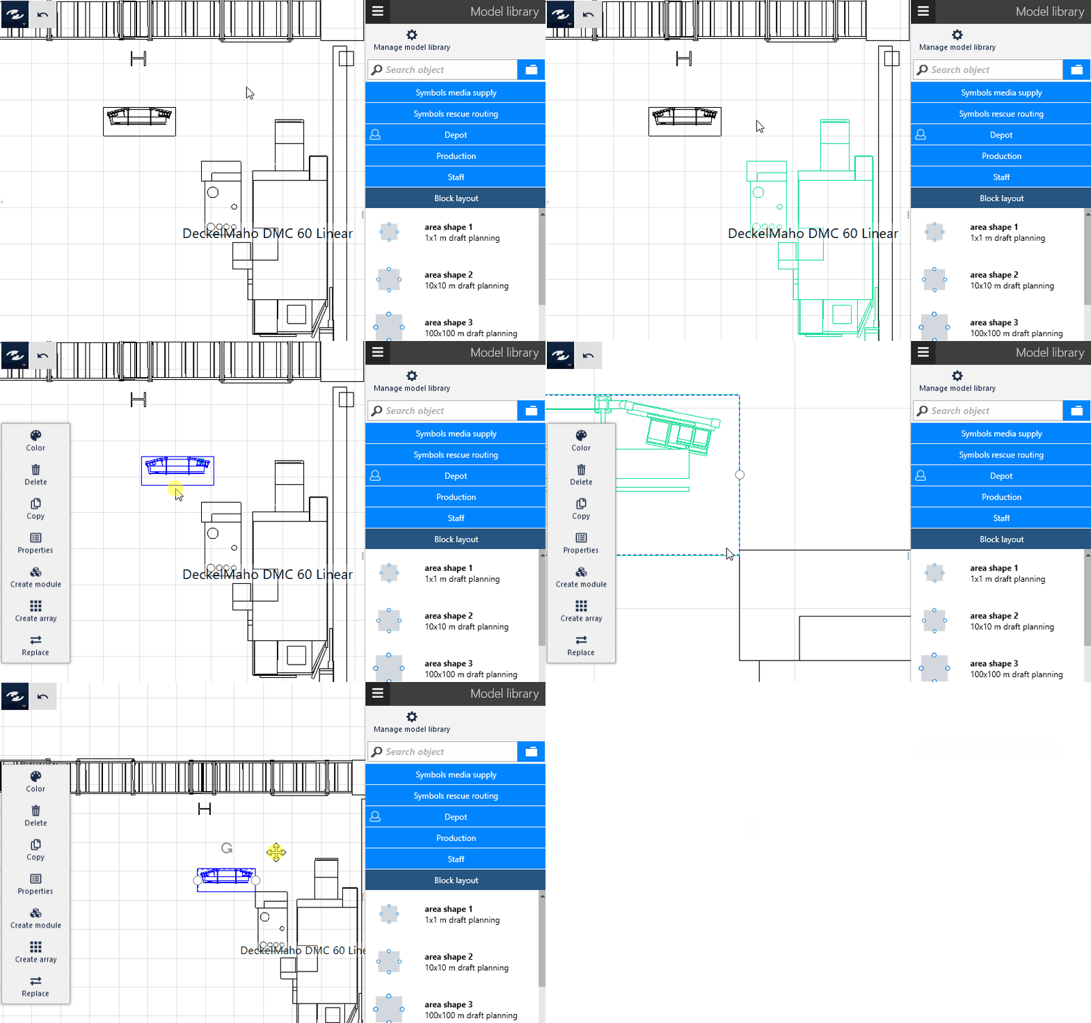
If the selected objects come close to other objects or to a line in the grid when they are moved interactively, snapping points are calculated and highlighted accordingly in color. The moved object can be snapped to the snapping points automatically. This feature is called Snapping objects.
- Move an object to another one or close to a grid line.
- Once a possible lock-in position is detected, the position is highlighted, and the moved object is locked into place automatically.
- If the detected position is not the desired one, simply drag the object further.
- Change the zoom factor when necessary and move the object to the target area again to reach other snapping points.
Practical tip
Use the CTRL-key whilst moving to quickly activate or deactivate the snap.
Interactive rotation
Two possibilities are provided for interactive rotation:
- Place the mouse or finger on the adorner displayed at the selection and drag in the direction where you wish to rotate.
- Press the
<Alt>key and simultaneously move the mouse or finger to the object or an existing selection and drag in the direction you wish to rotate.
Rotation increments
The farer you move the point of application of the mouse or finger away from the center of rotation, the finer will be the step width when rotating. Is 90° close to the center, farer away 15°, and on the outer edge 1°.
Interactive scaling
Interactive scaling is provided exclusively for objects that can be selected separately and for Background Images. Groups, text boxes and CAD Background Images cannot be scaled interactively.
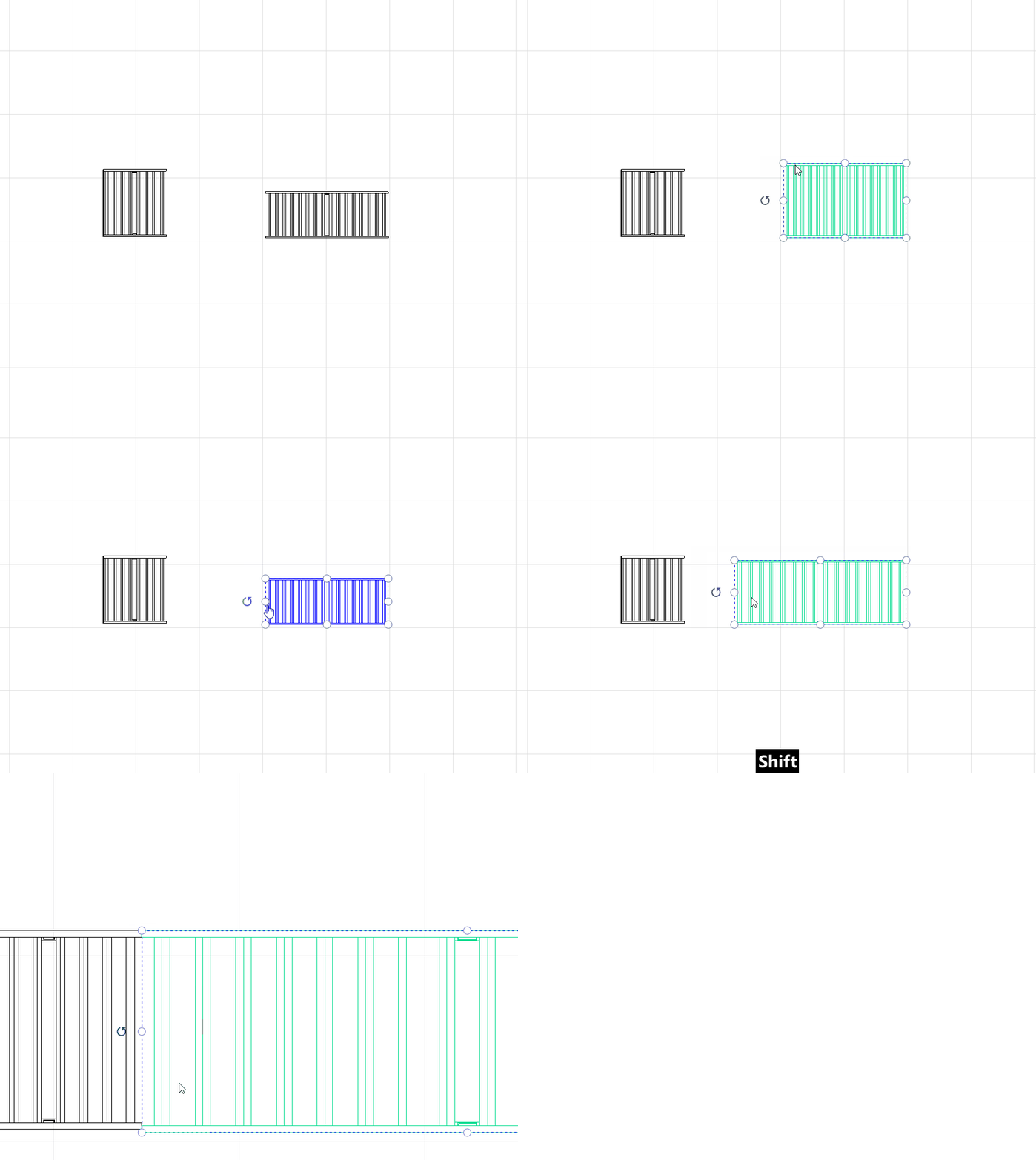
- Select an object.
- Specify an appropriate zoom factor to make visible the required adorners for scaling.
- Drag a scaling adorner in the desired direction. If the adorner is hidden when dragging, scaling can still continue.
- Change the zoom factor as necessary to continue scaling with higher or lower precision.
You can use the adorner in the corners to scale in length and width at the same time. Hold down the Shift key during this action to scale proportionally; the aspect ratio between length and width is maintained.
Move label
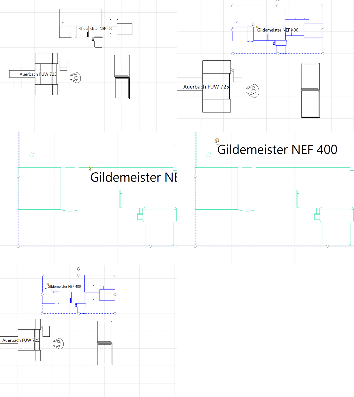
The yellow adorner is used to change the position of the object designation in relation to the center of the object. It can also be positioned outside the object contour. The designation remains aligned either horizontally or vertically so that all designations can be read from below or from the right. However, you can change the alignment via the Properties task area using the Dynamic menu.
Quick measurement
Use this action to quickly determine the distance between two freely selectable points in the layout area. Proceed as follows:
- Tap Quick Measurement
- Now tap the starting point of the measurement
- Then tap the end point of the measurement
- Read the measured value. With the next click, the measured distance disappears from the layout.
- Repeat steps (1) - (4) to take another measurement.
Zooming
To zoom in or out layout sections, normally, the mouse wheel is used. To this end, move the mouse on the point in the layout area which is to be zoomed in or out. Rotating the mouse wheel towards the operator will zoom in the layout section (and the objects appear smaller), and rotating the wheel from the operator away will zoom out.
The Pinch to zoom gesture is used as a touch hardware; two fingers are placed on the touchscreen. Opening the fingers will zoom out the layout section (the objects appear larger), and closing the fingers will zoom in (making the objects smaller).
In addition, zooming controls are provided in the bottom right corner of the layout area:
+: Zoom out layout section (the objects appear larger)-: Zoom in layout section (the objects appear smaller).Zoom to fit: When you double-click or tap the double-arrow symbol, it moves automatically to a zoom factor at which the selection is zoomed to fit the layout area. If nothing is selected, the zoom factor is fitted to the visible objects.
Pan
The visible layout section can be moved. Depending on the hardware, the following options are available:
- Press the middle mouse button and drag the mouse.
- Place 2 fingers on the touchscreen and then drag both fingers simultaneously at the same distance from each other.
- Permanently switch the left mouse button to Pan by briefly pressing
ALT GR(rightALTkey). This is necessary in the few cases where the hardware does not support a middle mouse button or touch gestures. Briefly pressingALT GRagain switches the left mouse button back to the standard function for selecting.
System menu
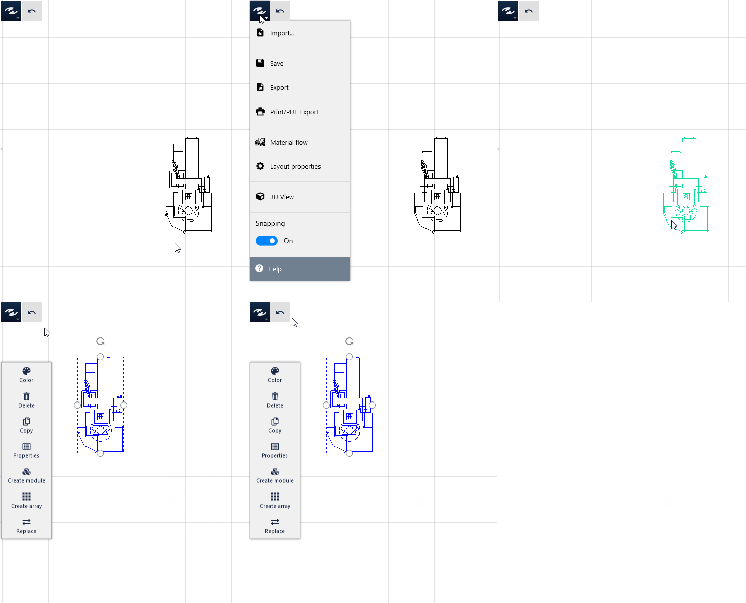
The system menu gives access to the Basic Settings and Functions to create, edit and save Layout Documents. Two buttons to undo and redo actions are provided immediately to the right of the system menu.
Actions in the system menu
When you move the mouse over the menu or tap on it, it is pulled down. The menu is closed by selecting an action or moving the mouse away.
Import: Provides appropriate possibilities to integrate geometry data from other systems into a Layout Document.Save: Saves the layout document in the file system in the VTLX format. You are always prompted to specify a name for the document (Save As ...).Export: Converts selectable parts of the Layout Document to a different format and saves it in the file system with a freely defnied name.Print/Export to PDF: Can be used to print 2D geometry data true to scale or export them to the PDF format. The scale and image section can be specified.Material Flow: Opens the task area with the same name for basic settings for display and for import/export of movement data. In addition, this task area comprises important Design and Evaluation Functions for the material flow.Layout Properties: Can be used to specify the sizes of layout and grid and, as an option, the project name and notes regarding the project; in addition, further information about the layout is displayed.Start 3D View: Starts the visTABLE®3D view if it is not yet opened.Snapping objects when moving: Controls whether or not geometric objects in 2D are automatically snapped to certain points when moved using the mouse or finger.Help: Opens the Home Page of the visTABLE® Program Documentation in the standard browser installed.
Undo & Redo
These two buttons can be found directly to the right of the system menu. The Restore action is only available if at least one action has been undone.
Practical tip
Please note that the effects of undo/redo actions are not always visible in the layout area, e.g. if the actions are performed with objects on hidden layers.
Dynamic menu
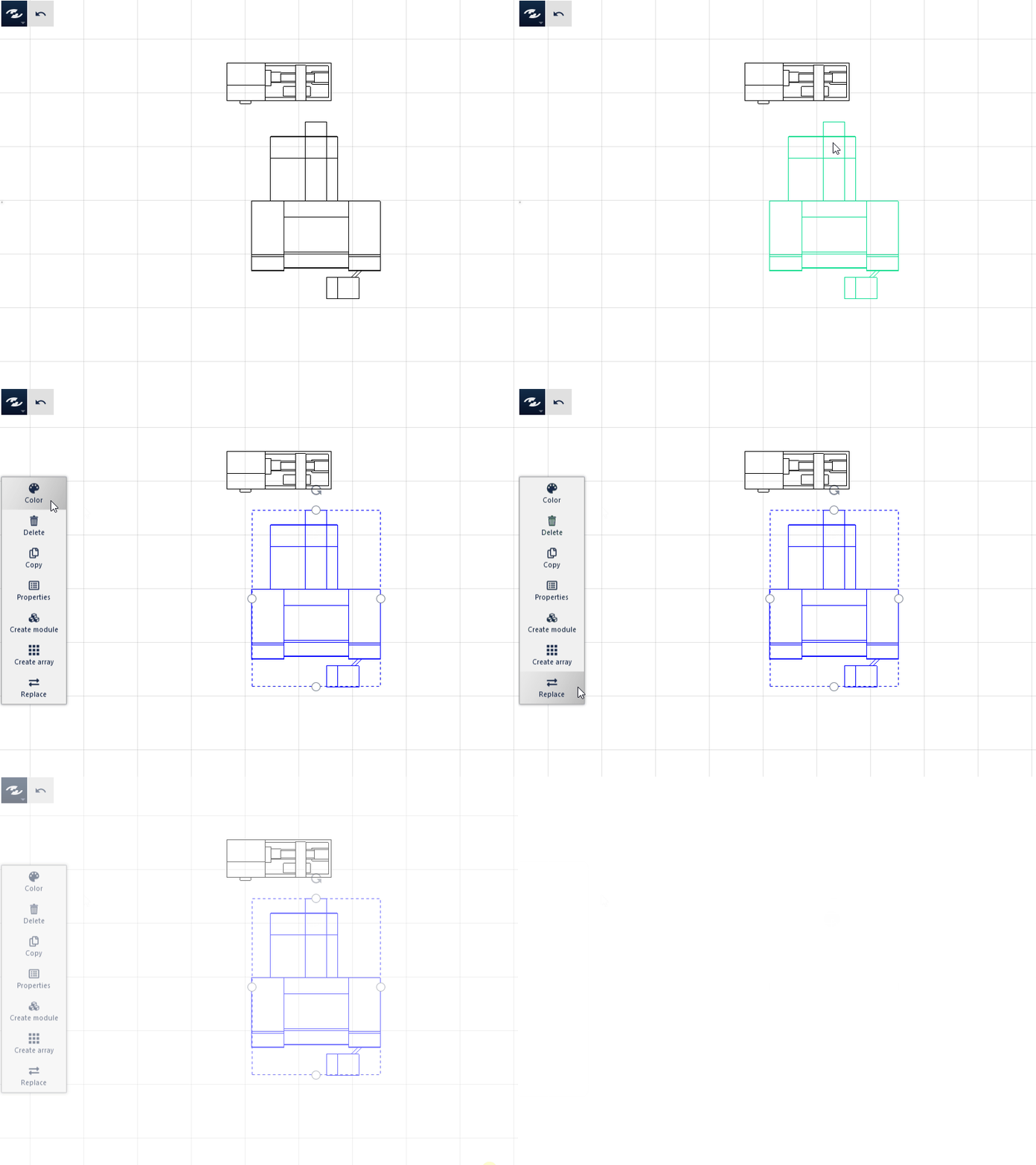
The dynamic menu is adapted in its contents in accordance with the type and number of the objects selected (highlighted) in the layout. Thus, the appropriate actions are always available.
Actions for individual objects
The following actions are only available if objects are selected separately.
Color: Usually changes the color of the bounding box for the selected object(s) in the layout area.Delete: Removes the selected object(s) from the layout. The same effect is produced by theDELkey.Copy: Copies the selected object(s) to any spot in the layout which can be selected by left-clicking or tapping. The shortcutsCTRL+C/CTRL+Vare also available, but cannot be used to position the copies immediately.Properties: Provides access to all changeable attributes of the selected object or to several objects as a whole. If the selection contains groups, thePropertiesaction grants access to the individual objects of the group e.g. to move, rotate or modify them otherwise.Remove from group: Removes the selected object from the group if it is part of a group. The action is only available if thePropertiesaction is applied to a grouping.Create array: Creates several copies of an object in the x, y or z direction with definable spacing by way of only one action.Replace: Is used to replace the selected layout object(s) with a model from the model library. Groupings are taken into account.
Actions for several objects
The following actions are (in some cases, additionally) available if several objects are selected at the same time.
Group: Summarizes all objects in a group e.g. to move them together.Ungroup: If at least one grouping is selected, it is ungrouped; only then you can access the objects contained therein separately.Create module: Can be used to summarize objects in a (Factory or Equipment) Module. During this process, the selected objects are saved in the model library and can be pulled in a layout as predefined groups later.Align: Can be used to align, distribute or arrange several objects at a defined spacing.
Actions for transport networks
The following actions are (in some cases, additionally) available if parts of Transport Networks are selected.
Select network: Can be used to select a complete connected Transport Network.Select direction: Defines the transfer direction on the Network Edge.Divide: Creates a new node in the middle of the network edge.
Task and tool area
This area displays general information and can be used for inputs required to process more complex tasks of operation in visTABLE®touch, e.g. the processing of the object properties in the layout. The Design and Evaluation Functions contained in the corresponding Task Menu help to systematically enhance and further develop the layouts.
Access to task areas is possible in two ways:
- Direct selection of a task by way of an action in a menu of visTABLE®touch.
- Switch to the previously used task area by way of the
Backarrow at the top next to theTask Menu.
Start of the task area is the Model Library. Once reached, there is no Back arrow to return to a previously approached task.
It is not possible to go to the Properties task area by navigating though previous tasks by way of the Back arrow.
- If this task area was activated, it is left automatically if no more objects are in the selection.
- If meanwhile a different task area is used, with exception of the model library, the
Propertiestask area is displayed with each new selection.
The task menu
It is generally possible to use the 2D templates of visTABLE®touch to design factory layouts very easily and evaluate by way of key figures. Correspondingly, its planning functionalities are divided into Designand Evaluation Tasks and can be called together with general tasks in a compact manner in only one menu, the Task Menu.