Basic tutorial 2: From block layout to ideal layout
This tutorial is intended for new users. It teaches basic steps for value stream integration in the block layout created in our first basic tutorial.
Introduction
As the central challenge in layout planning the layout objects are to be arranged. But how? The current layout does not give any conclusions how the production processes run and which connections there are between the workstations and storage areas. Why this is very important, you can see in the following video:
Therefore, the first mainstep is to enter the product and process information in order to take it into account during layout planning. This makes it possible to supply heuristics for layout optimization with process data. This in turn allows us to systematically improve the layout using the layout optimization algorithms implemented in visTABLE®. The layout optimization is the final mainstep to get the ideal layout.
Product and process information is collected by analyzing the (logistic) processes according to the principle of value stream analysis for product families. To do this, use the visTABLE®logix app. The next video shows how this works in principle:
For the example, we model the following information:
- 2 types of shafts
long shaft(100,000 pieces p. a. andshort shaft(85,000 pieces p. a.) are produced, each forming a product family. - The transports are done with the transport means type
forkliftin mesh box pallets (1,200 x 800 mm). - The
long shaftarrives as a blank from the receiving warehousestore INand goes through the operationsturning,grindingandpackingin a transport lot size of 10; after the packing station, the transport lot size decreases to 7 and the finished shaft goes to thestore OUT. - The raw material for the
short shaftis kept ready as bar material in thestore INand is taken to the saw in transport lot size 10. There, 2 shaft blanks are sawn from each bar. From there, theshort shaftgoes through the same production process as thelong shaftin the same transport lot size.
Step 1: Creation of a first product family
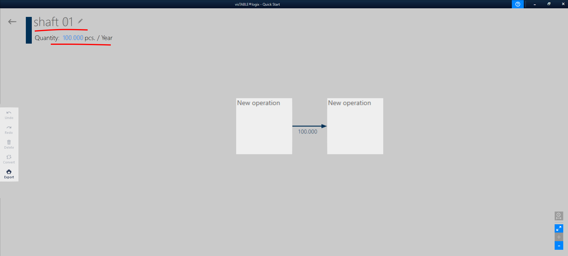
Open the visTABLE®logix app from the task menu. The app will show the production programm overview. Click on New product line. Please start with the long shaft (100,000 pieces p. a.) as shown in the picture:
Step 2: Define the value-adding operations
Then enter the individual process steps required to manufacture the long shaft. You have to use gestures to do that.
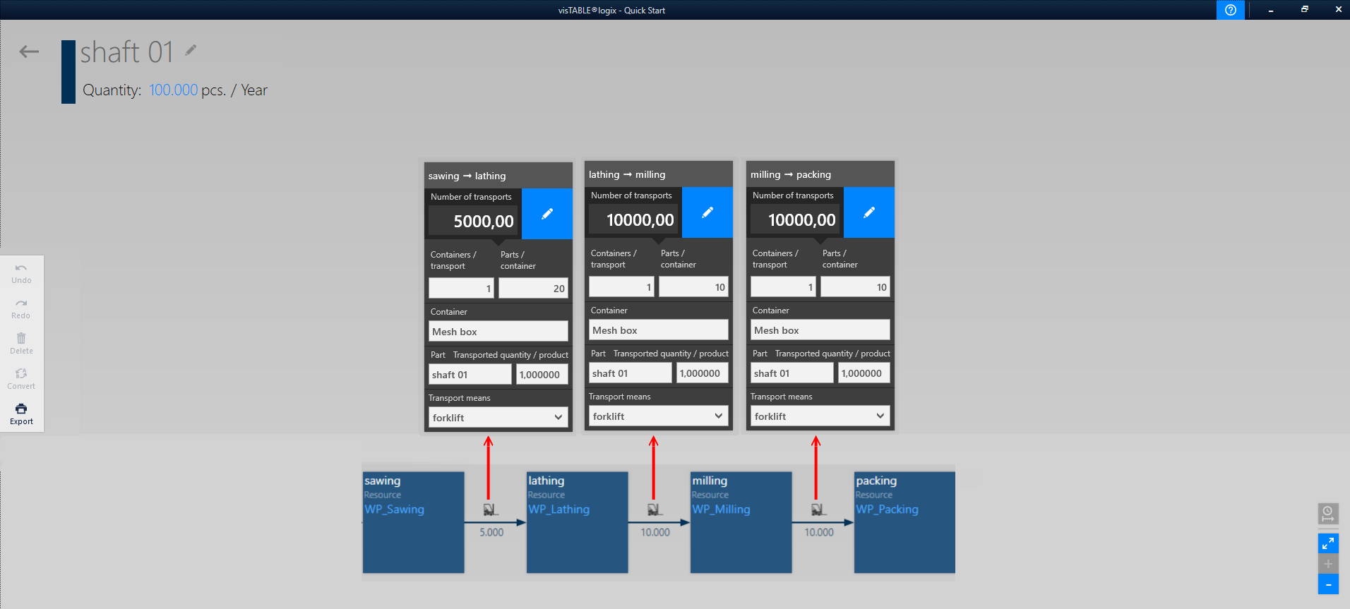
To make it easier to follow in our example, we enter the processes step by step and start with the value-adding processes, i.e. the operations sawing, turning, milling and packing. As resources, use the block layout areas, because the material is to be transported between the work centers. You can see the settings for the transport links in the following graphic:
Planning-tip:
In this example, assign the block layout objects as resources to all operations, not the concrete resources. This way you stay on the same hierarchy level, the block-layout, regarding the material flow model.
Step 3: Defining the peripheral operations
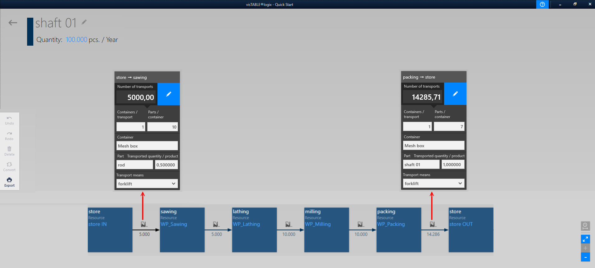
The non-value-adding or peripheral operations are also important for the overall layout, in particular the storage processes. The material or the products and parts have to be transported from the storage areas to the workplaces and back again. Thus, we complement the storage processes of the incoming goods warehouse and the outgoing goods warehouse.
Before the saws there is a bar material, which is sawn into two shaft blanks. Therefore, 0.5 bars (material) are required per shaft (product family). You can see the individual settings in the graphic:
Step 4: Adding missing operations and resources to the graph
Subsequently, the processes upstream and downstream of the warehouse processes still have to be added. The goods receiving and shipping departments are located outside the layout area we focus in the example. Therefore, these should not be planned as areas in our layout, but only serve as placeholders and interfaces to the outside. You can create the following operations for this purpose:
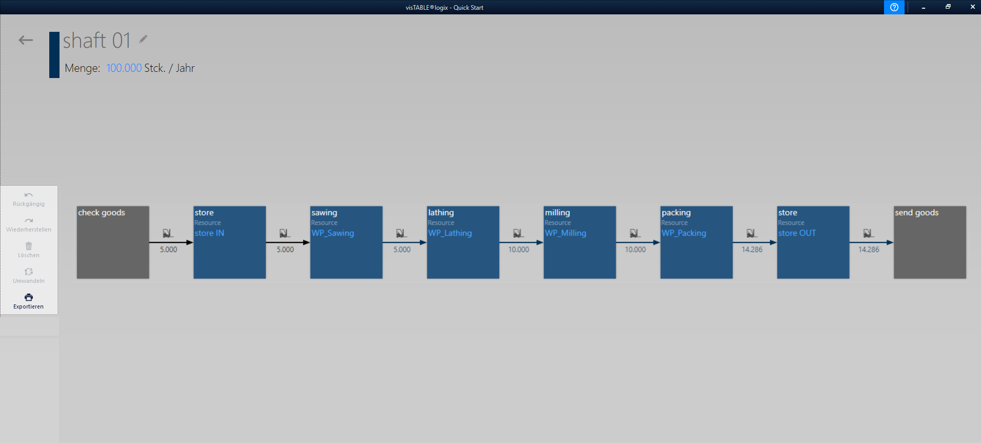
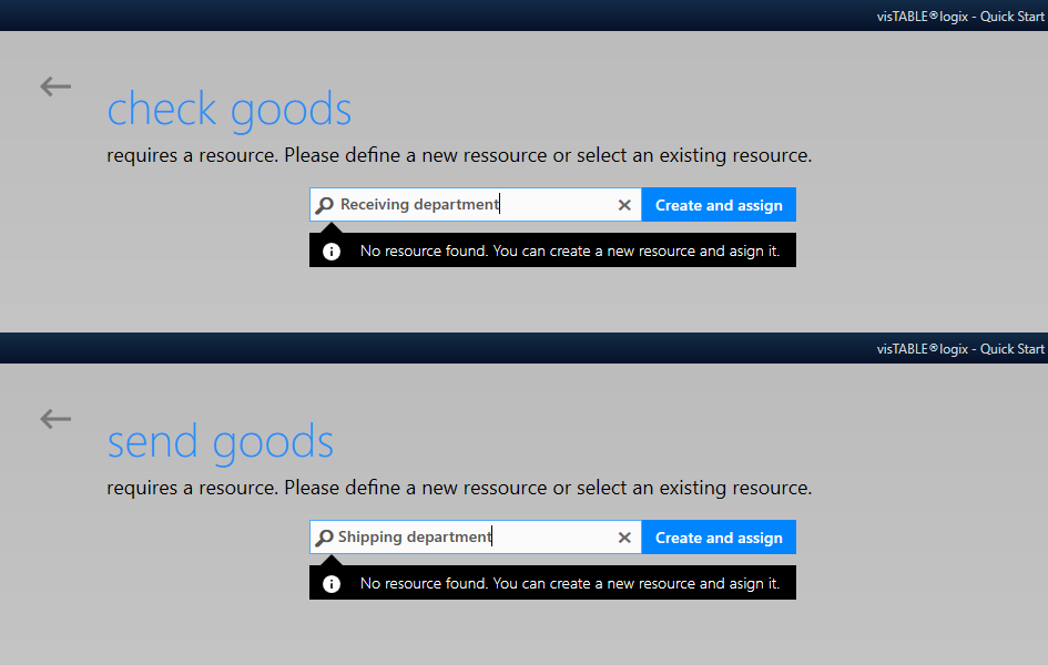
In the layout, no objects have been created yet for the goods receipt and the shipping department. In order not to have to interrupt the product and process input, we can create the layout objects in logix. When selecting the resources, enter the object designation (“Receiving department” and the “Shipping department”) and then confirm the entry with Create and assign:
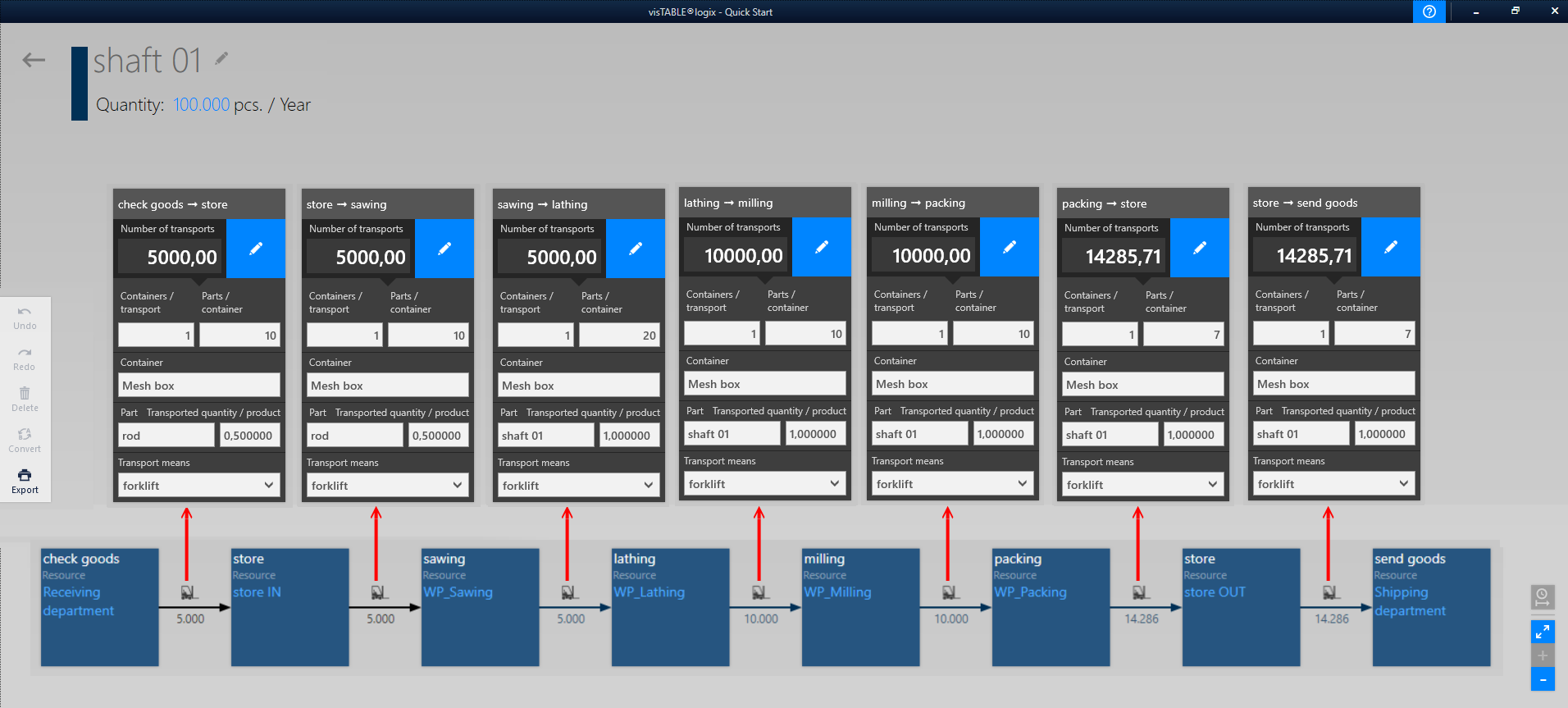
All the resultiing transportation properties are given in the next picture:
Step 5: Defining additional product families
To create additional product families you simply copy an exsting one. In our example we will only create one copy named shaft 2 for the shorter shaft. Please edit the graph of this product family as given in the introduction to this tutorial.
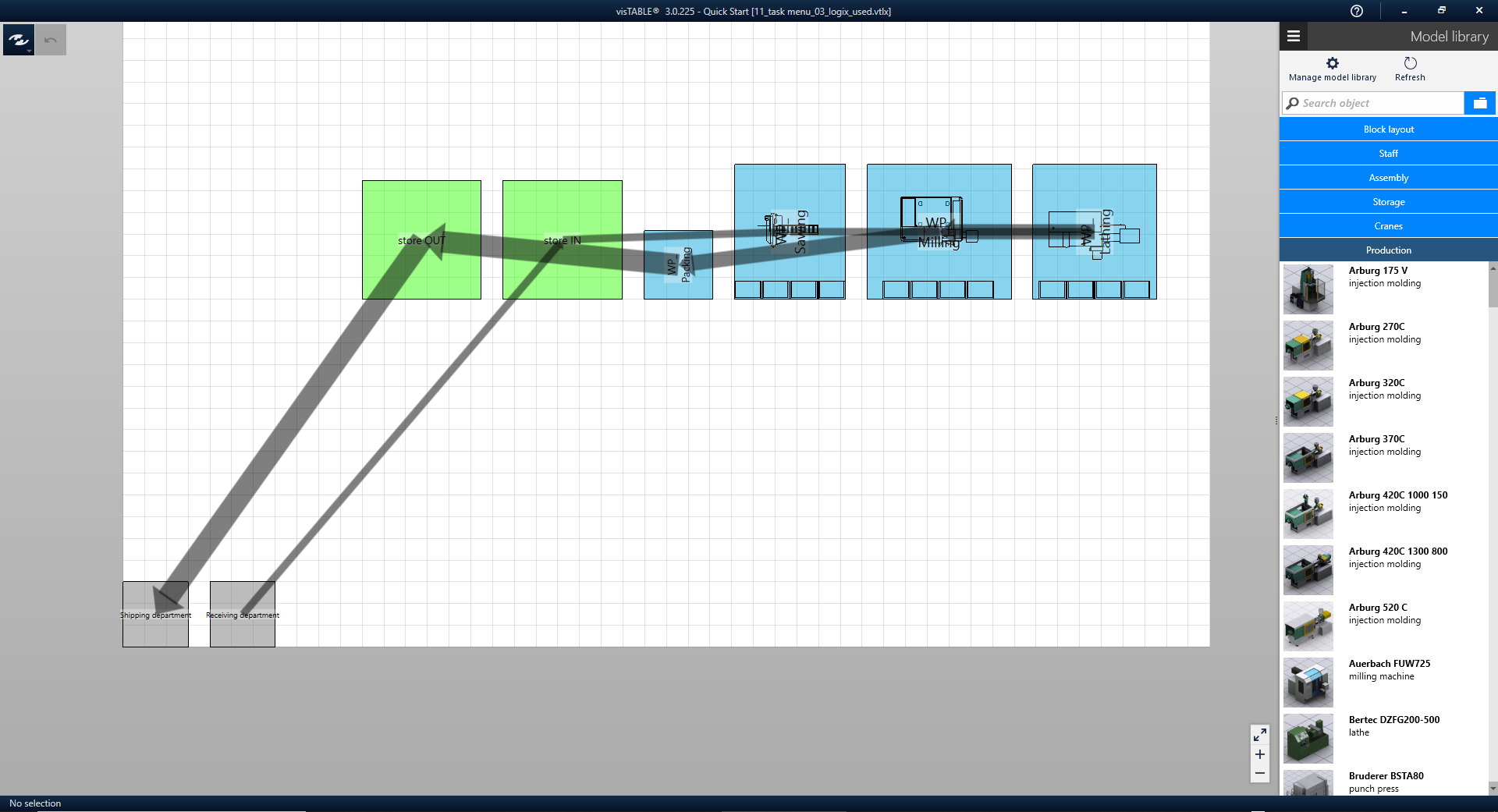
In the layout there is now the following situation. For the goods receipt and the shipping department placeholders have been created by the software itself. The placeholders are block layout objects arranged on the lower edge of the grid.
Step 6: Layout arrangement optimization
The next step is to determine whether the operating equipment is in a good position where it is currently located. To do this, it is necessary to investigate how many material flow relationships the blocks have to each other and in which intensity. Based on these two values, the visTABLE® design function arrangement optimization helps to find the ideal layout.
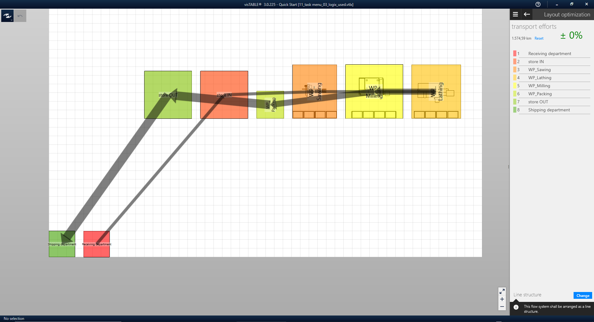
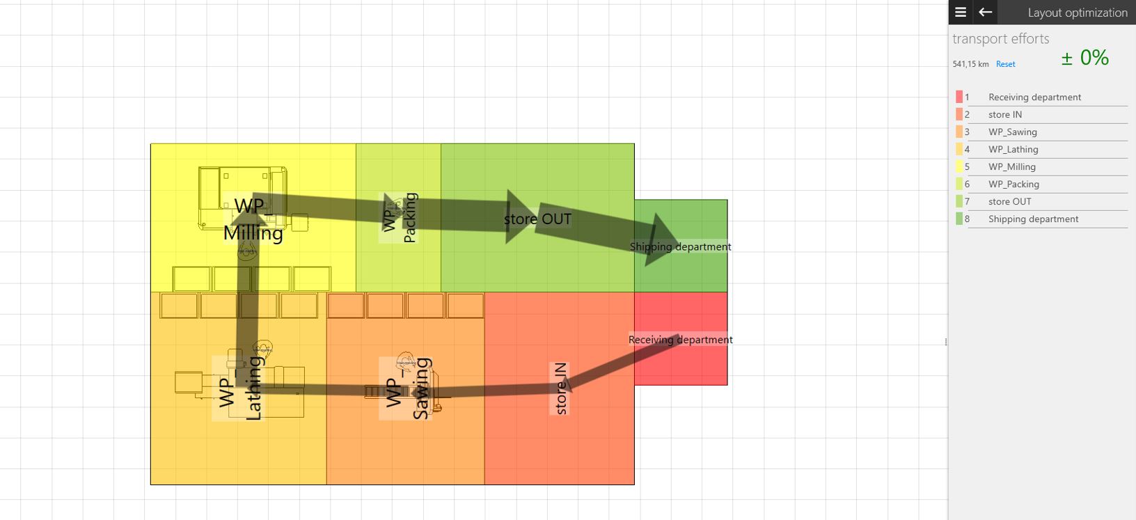
In the example layout, all blocks are traversed by material flows in sequence. Also, in the sum of all flow relationships, a linear structure is created. It is visualized in color in the layout as follows:
- The block with the darkest red must be at the beginning of the line,
- the one in rich green at the end.
- Everything else should line up from red to green along a line.
This order is also output as a list in the task area Layout optimization. Now it is only necessary to place this imaginary line into the available arrangement space and to arrange the blocks following the line. This is illustrated in the video:
In a first loop, the blocks can be ideally arranged as a line according to the proposed structure type. Make sure that you group the workstations beforehand. The transport effort is thus considerably reduced.

In further iterations, the ideal arrangement can be transferred step by step towards the real layout by taking restrictions into account. A first step here would be, for example, the transformation of the line arrangement into a U-, O- or S-shape.
Result of the tutorial
In our example, the layout is to be made more compact and thus transformed into a U-shape.
Are you satisfied with your result? Then the question now is how to transform the ideal layout to a real arrangement. Our next basic tutorial explains how this works in visTABLE®.
see also:
- What you should definitely know about Factory Planning (visTABLE®Blog)
- What means ideal plant layout? (visTABLE®Blog)