Importing models/catalogs
The “Import” function can be used to extend the visTABLE® Model Library by 2D and 3D models. This can be necessary if detailed layout with geometry data are to be created which are provided by suppliers or the user’s own toolmaking department.
Data complexity
Reduce the complexity of the data to the required extent prior to the import!
Ready-to-use 2D and 3D data can often be found in the construction. Construction data are, however, optimized for other purposes than for 3D representation in factory layouts. They comprise many (small) parts, structure information, materials, etc. which are of minor importance for layout planning and can thus not be used for factory layouts. Furthermore, such data require much computing power; long loading times, and delays in the representation can be the consequence. Attempts to reduce losses in performance due to the data complexity by way of hardware with higher performance mostly do not produce the desired results. It is usually not possible to reduce the data complexity by changing the import format even if files of the same object in different formats display significant differences in the file size - the contents do not change.
Supported formats
The visTABLE® Object Manager supports frequently occurring 2D and 3D formats. Furthermore, it can be used to exchange models in the proprietary visTABLE® formats VTC and VTM.
3D formats:
- Standard Tesselation Language (STL)
- COLLAborative Design Activity / Collada (DAE)
- 3DS Max File (3DS)
- Virtual Reality Modeling Language (WRL)
- STandard for the Exchange of Product model data (STEP)
- Initial Graphics Exchange Specification (IGES)
- Industry Foundation Classes (IFC)
- Drawing Interchange Format (DXF)
- AutoCAD Drawing (DWG)
- Wavefront (OBJ)
- Jupiter Tessellation (JT)
2D formats:
- Drawing Interchange Format (DXF)
- AutoCAD Drawing (DWG)
Formats for exchange between visTABLE® libraries:
- visTABLE® Model (VTM) (data exchange between visTABLE®touch libraries)
- visTABLE® Model Catalog (VTC) (data exchange between visTABLE®touch libraries)
Notes for preparing AutoCAD data for import
- A DWG/DXF file basically transformed into a model.
- All entities comprised in the model space are summarized in a model.
- Paper spaces contained in DWG/DXF files are ignored.
- All elements that are not relevant for the task should be deleted. A rough point for orientation is the file size: The smaller, the better.
- Supported entities: Point, Line, Arc, Circle, Ellipse, AttributeDefinition, Text, MText, Polyline, Polyline2D, Polyline3D, Spline, Face, PolyfaceMesh, PolygonMesh (Simple, with no surface fitting or smoothing), MInsertBlock, BlockReference, RotatedDimension, AlignedDimension, RadialDimension, DiametricDimension, Solid, Solid3D, LoftedSurface, Region, Mline, Hatch, SubDMesh, RasterImage, Body
- Proxy AEC objects are not supported and must be exploded in advance. To do this, use the “-EXPORTTOAUTOCAD” command in AutoCAD Architecture, which converts the proxy AEC objects into AutoCAD basic objects. It is important to switch to a 3D view before exporting, otherwise the proxy AEC objects will only be exported as 2D derivatives.
- Cleaning the file: File > Command > Clean, All.
- You should also use the troubleshooting function of the CAD application (Audit or similar).
- Dissolve all blocks/block references.
- Dissolve all text blocks.
- Remove all hatches.
- Use the “Zoom Extents” command to identify elements lying far outside the drawing area and delete them where necessary.
- Leave only entities in the drawing which are relevant for the model.
- Save in AutoCAD DXF or AutoCAD DWG format.
- Make sure that the file name does not comprise umlauts, special characters, etc.
- XREFS are not supported and must be bound. Use the command „XREF“ in AutoCAD and „bind“ afterwards.
Procedure
The steps required for the import are controlled by the visTABLE® Object Manager. Proceed as follows to import a 3D object.
Except for importing data in the VTC or VTM format, check before starting the import how far the data comprise what you expect. To this end, the import file should ideally be opened in a source application suitable for saving the file in the desired format, e.g.:
- AutoCAD or DraftSight for DWG, DXF;
- SketchUp, MeshLab or Blender for OBJ;
- 3DS MAX for 3DS;
- Blender or 3DS MAX for WRL, OBJ;
- FreeCAD, Blender or 3DS MAX for STL;
- FreeCAD, CATIA, SolidWorks or Solid Edge for STEP;
- FreeCAD, AutoCAD, TurboCAD or Nemetschek Vectorworks for IGES;
- Paint for BMP.
Step 1:
Select
- the target library and
- the target catalog
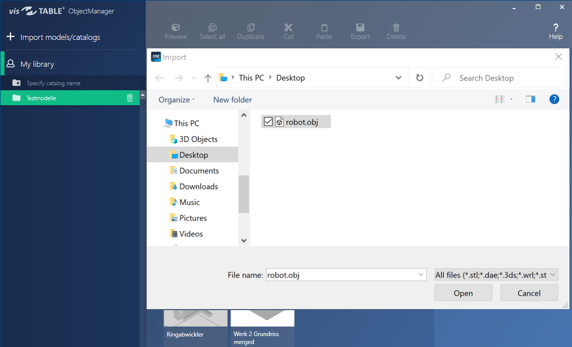
and start the Import Wizard. The Import Wizard is started by way of + Import models/catalogs in the top left corner. Then select the file to be imported in the Windows® file selection dialog displayed after this action.

Note
If no target catalog is selected, only the import of data in the VTC format is available. A file in the VTC format comprises a complete visTABLE® catalog that is added by the import of the currently selected User Library.
Step 2:
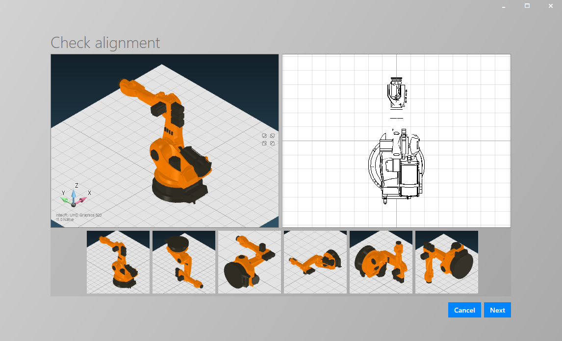
After a certain time of computing which is normally short, a preview of the import object is displayed. It serves for checking the orientation of the import object in the space.
- The currently selected orientation is shown by the upper two illustrations - on the left in 3D, and on the right in 2D. You can view the model in the 3D view from any positions by moving the mouse while holding down the middle mouse button. To zoom in or out the model, use the mouse wheel. To reset the zoom factor and orientation to a standard value, tap on the symbol with the 4 arrows.
- The 6 possible orientations (standing, 4 x tilted, and upside down) are displayed as thumbnails below.
To correct the orientation, select the thumbnail below which displays the expected orientation in the 3D factory layout. Subsequently, the corresponding 3D and 2D previews are displayed in the upper part. If the model to be imported is standing upside down, for example, select the thumbnail below which corresponds to the correct orientation.
Select Next to go to the next step. Select Cancel to cancel the import process.

Step 3:
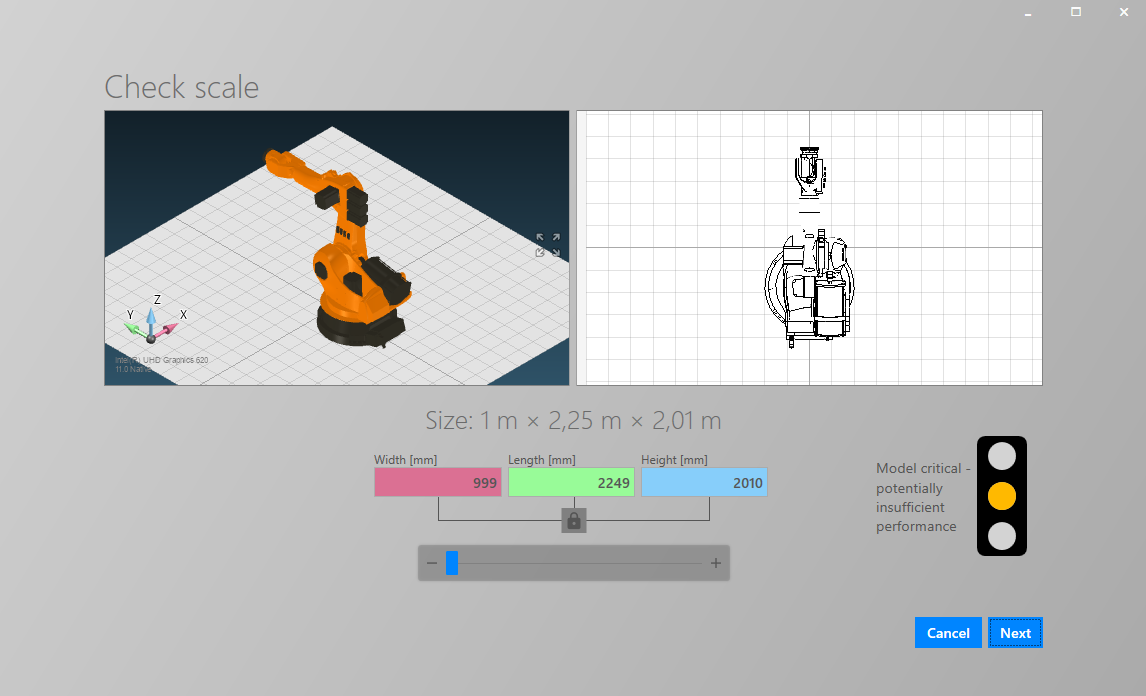
Check first the scale and then the complexity of the object to be imported.
The size of the model displayed under the image should correspond to the expected value (real dimensions of the object). Otherwise,
- use the controller to increase or reduce the scale step by step by the factor 10,
- specify a known dimension to set the target dimensions for the object. The dimensions are scaled proportionally, i.e. each dimension is adapted to the other ones at the same ratio when one dimension is changed by the input.
Subsequently, the complexity of the model can be evaluated by way of the color of the traffic-light indicator and the intended purpose.

Colors of the traffic-light indicator
If the traffic-light indicator displays YELLOW or RED, cancel the import and prepare the model in accordance with the notes given above.
Click on Next to complete the import. Select Cancel to cancel the import process, e.g. to reduce the complexity of the model. If you nevertheless select Next even if the traffic-light indicator displayed yellow or red, a warning note is displayed, and you have one more opportunity to cancel the import process.
Step 4:
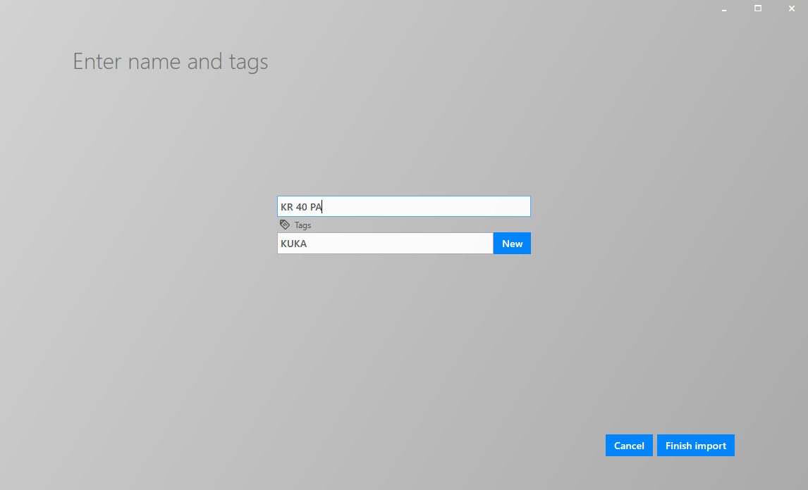
Finally, specify the name for the model and the search terms.
- The name is used to identify the model in the model library.
- Search terms are displayed in the visTABLE® Model Library with their names.

The computing process can take a little time, depending on the degree of complexity of the model.
Results
When the model has been imported successfully, the model or the catalog is available both
- in visTABLE® Object Manager and
- in visTABLE®touch.
If the model is not visible in visTABLE®touch in the expected catalog, refresh the appropriate model library. To this end, use the Refresh function located above the model library (only available if the catalog overview is displayed).

The model can be modified at any time after the import in the Properties Area. Such modifications have no influence on objects that are already used in the layout (the object properties are not inherited from the library to layout objects).
Batch import
To import several files simultaneously, select them in the file dialogue. For the first file, enter the settings as for the normal import. The selected settings for alignment and scale are applied to all files.
Colouring
If the model is a surface model with certain material properties (single material or materialless e.g. STL format), the model can be colored in the layout.