Processing a product family
Forming product families
The configuration and method to form a Product Family is solely your own decision. Thanks to that, the software can be used in many projects with different methods and strategies. It is, however, to be observed that the efficiency, ability to control, reaction speed and further procedure in the planning process for the system to be planned is decisively influenced by the ways and methods how parts and materials are summarized in product families.
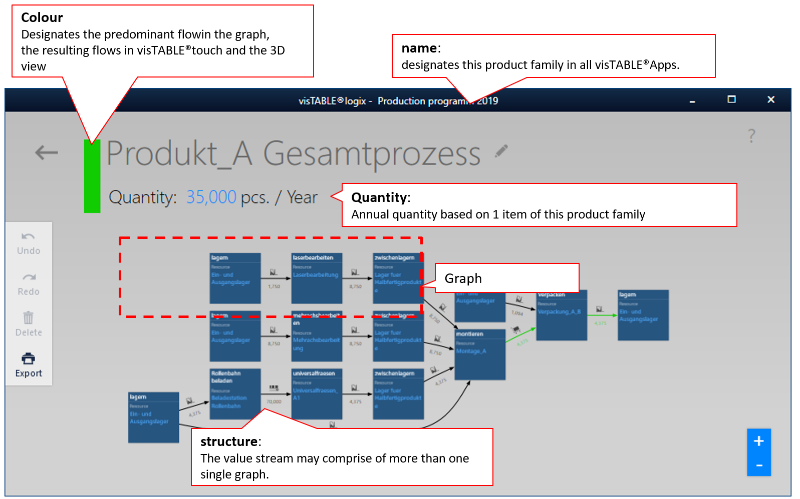
All Product Families are displayed in visTABLE®logix in the Product Family View. A product family is characterized by
- a designation (name of the product family),
- an output quantity (annual quantity) for the entirety of parts or materials described by it,
- a structure, the so-called product flow which can comprise one or several graphs and
- a color coding.
Designation and annual quantity
The designation and output quantity p.a. are displayed in the top-left corner of the Product Family View.
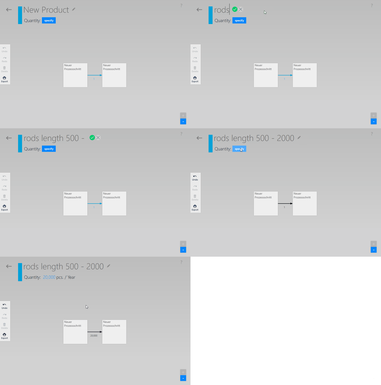
- The quantities to be transported (can be identified e.g. by way of the transport arrows in the product flow charts) are always calculated automatically for all transports of the product family, depending on the specified annual quantity.
- The color coding to the left of the name of the product family
- Highlights the main flow in the product flow in visTABLE®logix; These are the transports for the main part of the product family (e.g.a mounting plate on which the components are mounted). In the
Transporteditor, the product family designation ispartof the main flow transports. - Highlights the flows in visTABLE®touch and in the visTABLE® 3D view which result exclusively from the appropriate product family.
- Highlights the main flow in the product flow in visTABLE®logix; These are the transports for the main part of the product family (e.g.a mounting plate on which the components are mounted). In the
Practical tip
Specify first the names and annual quantities for new product families and start only then with the acquisition or modeling of the product flow structure. The annual quantity can be adapted at any time e.g. to changed turnover forecasts by overwriting the blue value.
Creating and editing the product flow
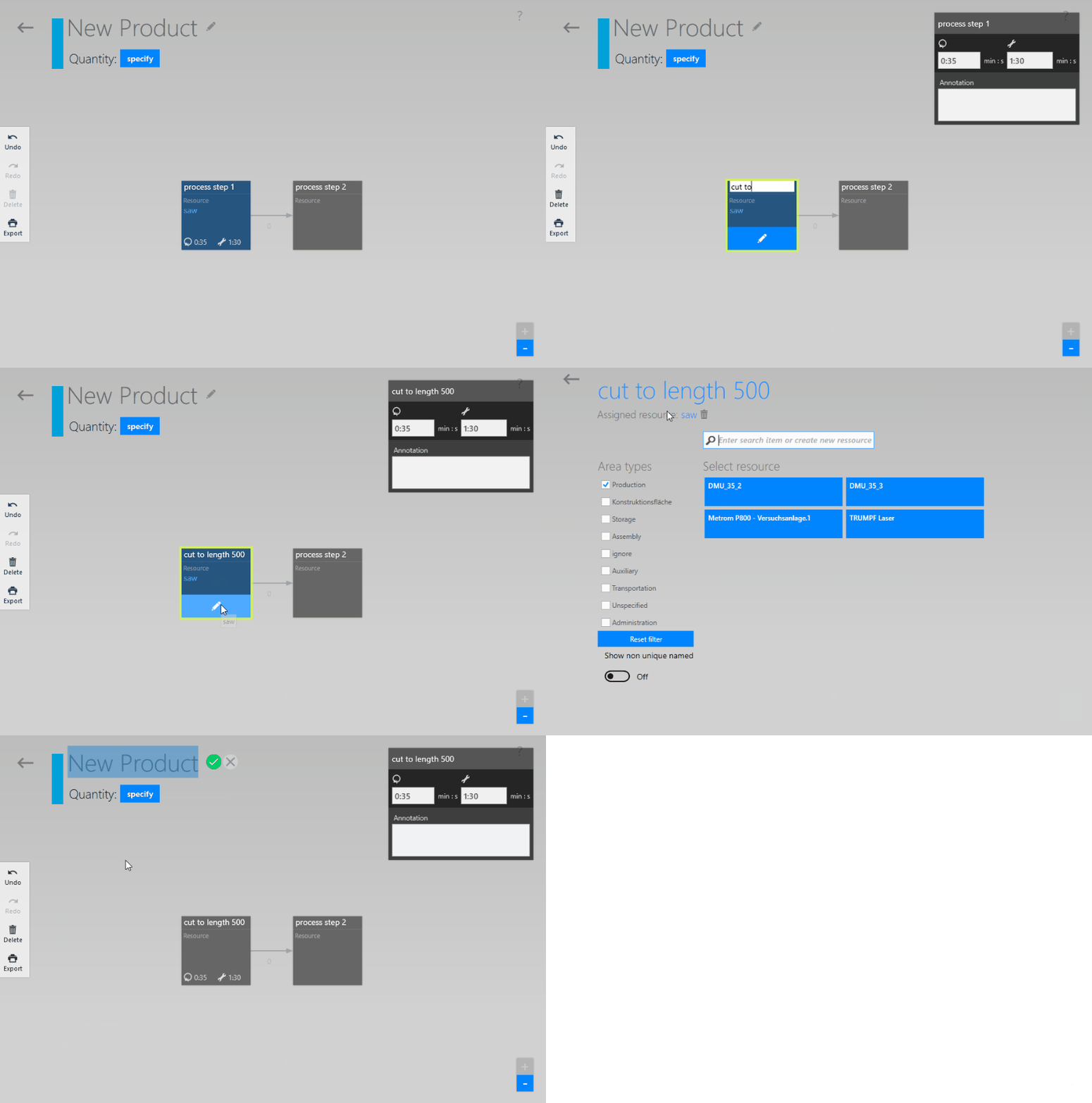
visTABLE®logix creates a chart to support you in describing the product flow. When you open a new product family, two empty Process Boxes with a Transport Arrow between them are already displayed. The arrangement of the symbols for the process steps and transports is initiated by way of gesture control and performed in visTABLE®logix automatically.
The
+ name of the operation and the
+ Resource Assignment
are changed directly in the Process Box.
Practical tip
It is best practice to use nominalized verbs for the operations (activities) and nouns for the resources (scene). Examples:
- Name of operation: Assembling, disassembling, packaging, order picking, etc.
- Name of the resource: Assembly, disassembly, packaging, order picking, etc.
Further specifications regarding the product flow are acquired by way of special editors for data input. To open such an editor, left-click or tap on the Process Box icon or the Transport Arrow which are both located in the top right corner of the Product Family View.
Process Stepfor planned time values for operation and notes regarding process steps.Transportfor the parameters required to determine the number of transports.
The Process Step editor
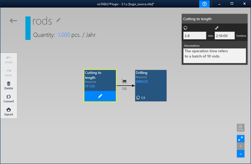
Use this editor to acquire planned time values, circulating stock and notes for process steps where necessary.
- Circulation stock can only be entered for warehouse operations.
- The left time input field can be used as operation time for the throughput view. The right time input field is used to document setup efforts. Its time value does not flow into any calculation.
Minutesorhh : mm : ssare used as the time format (cf. illustration: Selected process boxCutting to length).- The assigned time or stock values will be displayed at the bottom of the process box once you have quit the editor by selecting another process box (cf. illustration: Process box
Drilling).
Legal note
The recording and saving of measured (actual) times by way of appropriate software is subject to co-determination rights within the meaning of Section 87 (1) Para. 6 of the German Works Constitution Act (“BetrVG”). visTABLE®logix is not designed for the recording of such times, but exclusively for the documentation of planned time requirements (target times).
The Transport editor
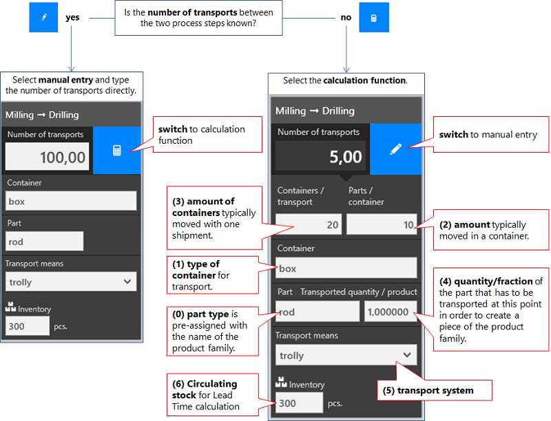
The number of transports per planning period (1 year) can be determined either by way of a calculation function or manually, depending on the progress in the planning and/or the level of knowledge regarding the logistic system:
Practical tips
- To calculate the KPIs for Logistics Assessment and Layout Optimization, the value of the number of transports is used which is displayed in the editor after tapping on the transport arrow. This is also the value that can be seen directly on the transport arrow.
- If the calculated or manually entered number of transports is zero, the transport arrow is represented semi-transparently. Thus, the transports that are not yet described completely can be identified in the product flow chart easily.
- If the annual quantity for the product family is changed, this will influence both the calculated and the manually entered number of transports since the reference quantity of the two values also changes.
Explanations regarding the input fields:
- (0)
Part: The default entry in the field for the part type (0) is the name of the product family. In this case, transport is to be understood as a part of the main flow for the product family. If, however, supply or waste disposal transports of e.g. components or packaging materials are modeled, these part types can be specified here to highlight the subsidiary flow. In this case, the transport arrow in the product flow chart is highlighted in black, otherwise, in the color defined for the product family in the top left corner next to the name of the product family. Part types that deviate from the designation of the product family are summarized in the Parts Overview (View of the Production Program). - (1)
Container: If a transport aid is used, it is identified by the container type (1). This specification facilitates the traceability in the fields (2) and (3). If the container type is not known, diverse, or there is no container type for the appropriate transport,Not definedis specified here as the default value. This mandatory field can also be used to identify the transport unit by way of specifications such asSet,BundleorBag. All containers are represented in the Container Overview (View of the Production Program). - (2)
Parts/Container: The input value (2) is used to calculate the number of transports by dividing the annual quantity by this value. For example, if 10 parts are transported each in a container for an annual quantity of 1,000 parts, the number of transports would be 100 p. a. if all the other input values are1. - (3)
Containers/Transport: This value describes the transport unit. The value (3) specifies how many containers are required for thepartconcerned to form a transport unit. This input is used similarly to value (2) to calculate the number of transports p. a. for the product family. - (4)
Transported Quantity/Product: The value (4) that is to be entered here not necessarily specifies the frequency of occurrence of a part in the final product. The value must take into account the frequency of the part to be transported between process steps. This also includes, but is not limited to necessary reworks or the scrap in later production steps in the process chain.
For example, if a part with quantity 4 is incorporated in the final product, but an average scrap of 20% was determined in the last process step (final assembly), then 5 parts each are required in the preceding process steps to be able to realize the required 4 parts per final product. Consequently, this part must be specified with a transported quantity of 5 for all transports of the process chain. As far as this example is concerned, the part typeScrapis modeled with a transported quantity of 0.2 per product, referred to the product family in a waste disposal transport. - (5)
Transport Means: Here, a Transport Means specified in the List of Transport Means must be selected. This influences which route (defined by way of Transport Networks) is used by the flow of this transport in the layout. The type of transport means is visualized in the product flow chart on the transport arrow unless the typeMiscellaneousis selected. - (6)
Inventory: The input field is only available for Lead Time View. Its value defines a circulating stock (actual or target value) between two operations, if it is not to be recorded in stock operations. This simple type of inventory modeling is common in value stream analysis.
Note that the transportation quantity (product of the values from (2) and (3), effective as a transportation lot size for some transportation equipment types) also forms circulation stock. Transport quantity and stock must independently reflect the conditions in the flow of goods.
Practical tip
When entering the key numbers for the transports, you should not only rely on the information from the ERP system, but (at least on a sample basis) check the actual number and organization of the transport process directly on the site.
Assigning resources
The operation described by way of the process step is linked with a Layout Object in the layout by assigning resources. The layout object is thus to be understood as a resource in the material flow. A resource can be assigned to several operations e.g. If the resource is used by several product flows or used several times in a product flow.
When you tap on the Pen Symbol in the bottom left corner of the Process Box, the user interface explained in the illustration below and used to link a process step with a resource. Is opened.
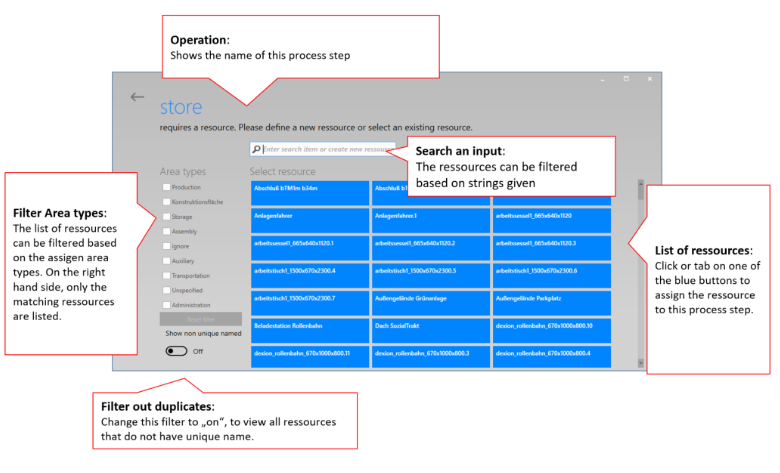
Generally, there are two possibilities to assign resources:
A process box is assigned a resource that already exists in the layout.
- All resources that can be assigned are contained in the
Resource List. Left-clicking or tapping on one of the blue name fields assigns the appropriate resource and switches back to the view of the product family. - If the list is too comprehensive, a filter can be applied by entering appropriate characters in the
Search and Input Field. - For targeted search for resources of a certain area type, the
Area Type Filtershould be set correspondingly. Then only resource names belonging to the selected area types are listed in theResource List. - If the searched resource is not contained in the list, it is recommended to use the
Duplicate Filterto check that the searched resource is designated unambiguously.
- All resources that can be assigned are contained in the
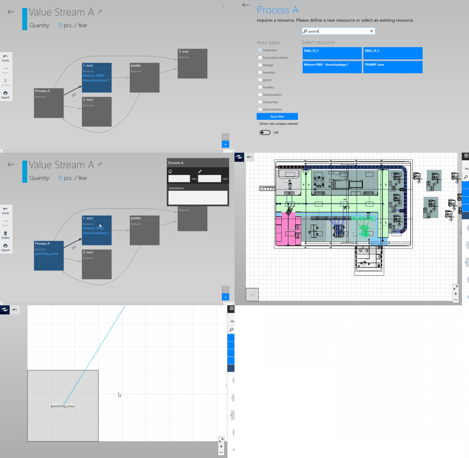
A process box is assigned a new resource which does not yet exist in the layout.
- The desired resource name must be specified in the
Search and Input Field. - If the resource name is not yet assigned in the layout, the
Create and Assigncommand is displayed. Left-clicking or tapping on it creates an area with the dimensions 3 x 3 x 0.01 m in the bottom left corner of the Layout Area of visTABLE®touch which bears the selected name. It acts as a representative of the new resource and can subsequently be edited in the Layout Area of visTABLE®touch.
- The desired resource name must be specified in the
Resources can be reassigned at any time by way of possibility 1 or 2 above.
Resource names
When creating the layout, make sure that the resources are designated unambiguously. If the layout comprises several resources with the same name, the resources cannot be assigned unambiguously since the resource name in the layout is the only key attribute to which you have access.
The Duplicate Filter helps to identify not unambiguously designated resources in visTALE®logix. If the filter is activated, all resources of the layout are displayed and highlighted as follows:
- The unambiguously designated resources in blue, and
- The ambiguously designated resources in gray.
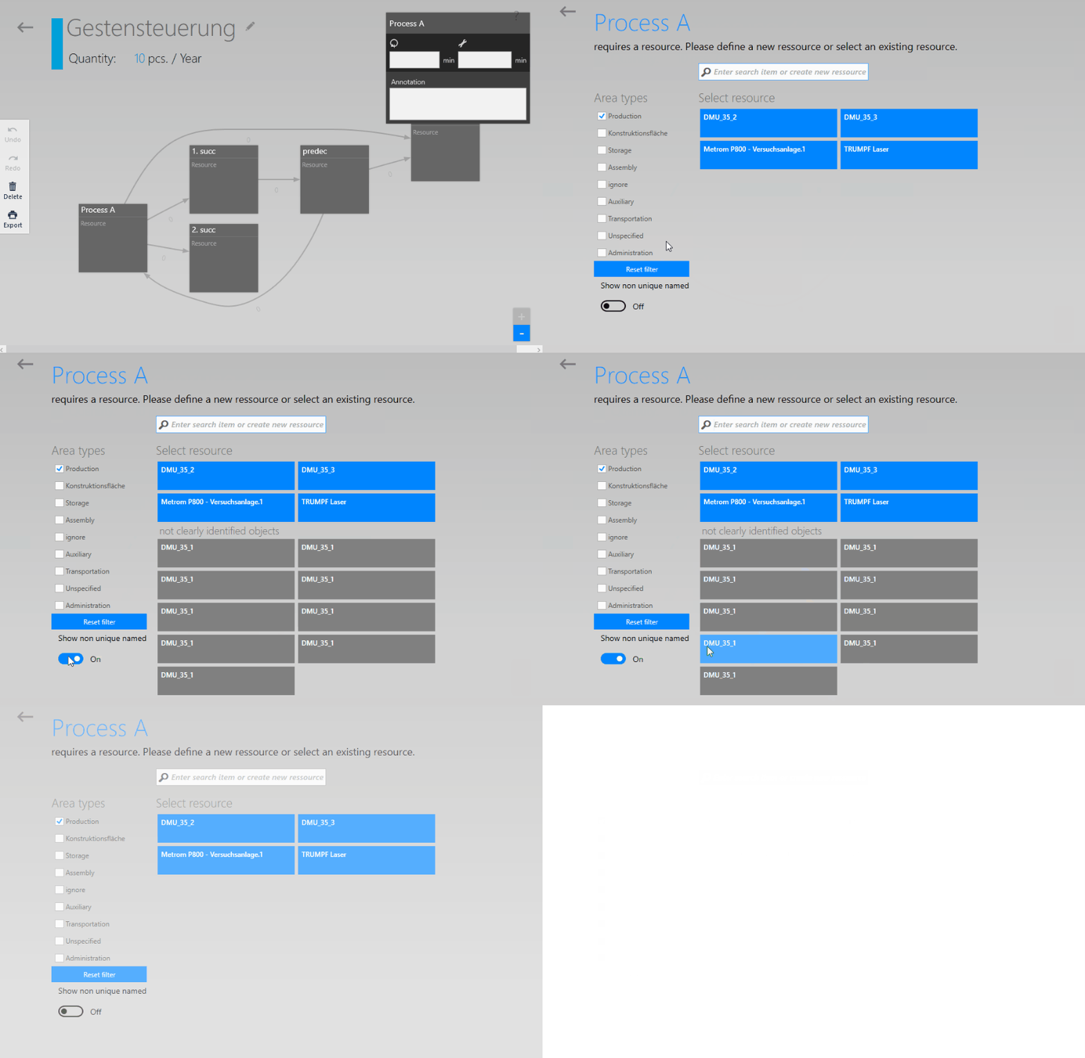
visTABLE®logix and visTABLE®touch together ensure that the material flow only contains unambiguously designated resources (so-called Flow Objects). Hence, exactly one not unambiguously designated resource can be assigned so as not to violate the rule. This is possible by selecting the resource from the list comprising the grayed resource names. This is, however, only recommended as an exception to be able to handle special cases in the layout model (e.g. to compensate of unfavorable hierarchy formation in ERP).
Gesture control
Interactive gestures are used to build up graphs (e.g. on a touchscreen). They can be used to control e.g. the actions specified below. When you click on the ? in the top right corner of the window , an animation film is shown to explain the gesture control.
Deletion
Complex structures can be deleted from the chart very easily by wiping once or several time with the finger (erase gesture). This is not recommended for use with very dense graphs, as the graph is recalculated after this gesture, and it may be difficult to recognize whether only the desired structures were deleted. Should this happen inadvertently, you should immediately use the “Undo” function in the dynamic menu on the left.
Deleting specific items
If an element of the graph is selected, you will find a recycle bin symbol on the left in the dynamic menu. Clicking or tapping on the recycle bin deletes specifically the selected process box or transport.
Actions
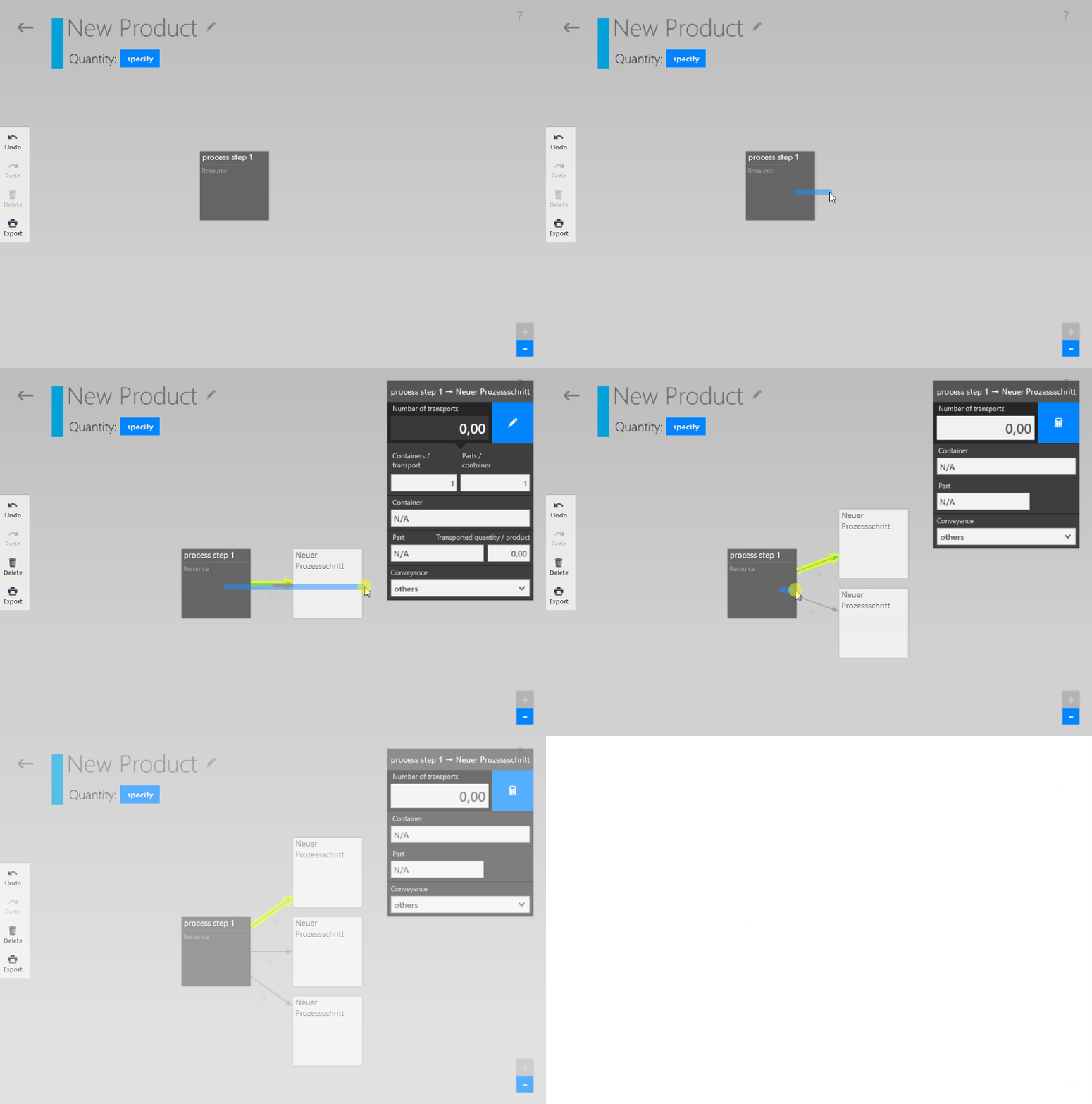
Creating a downstream process box, starting out from an existing process box:
Place your finger or the mouse pointer in the lower area of a process box and drag horizontally to the right. The movement must not end in another process box.
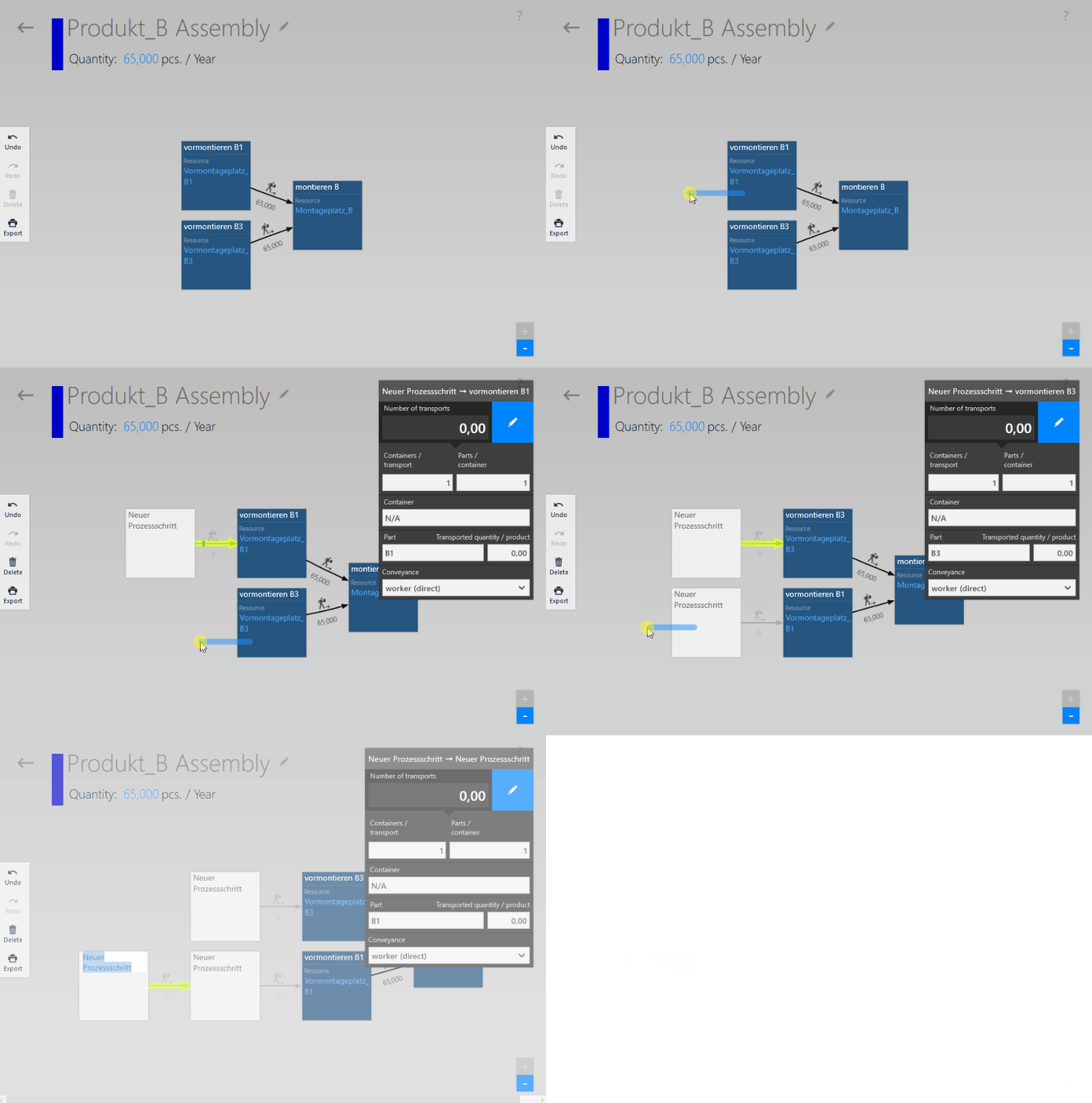
Creating an upstream process box, starting out from an existing process box:
Place your finger or the mouse pointer in the lower area of a process box and drag horizontally to the left. The movement must not end in another process box.
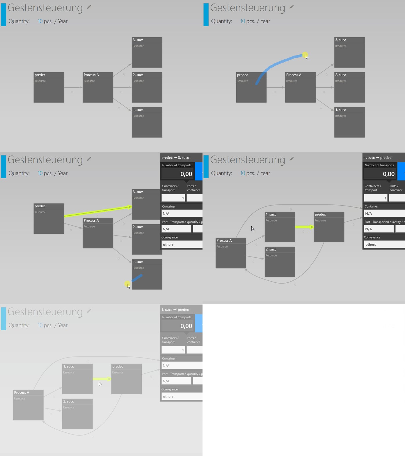
Reconnecting two existing process boxes:
Starting out from the process box you wish to be the upstream process box, place your finger or the mouse pointer in the lower area of the process box and drag to the process box you wish to be the downstream process box. It is not relevant if you move your finger or mouse over existing parts of the chart; only start and end of the movement are decisive. It is also not relevant where the appropriate process boxes are currently located in the chart. In other words: A process box left to another one can thus also be defined as a downstream process box. The chart is recalculated after this process.
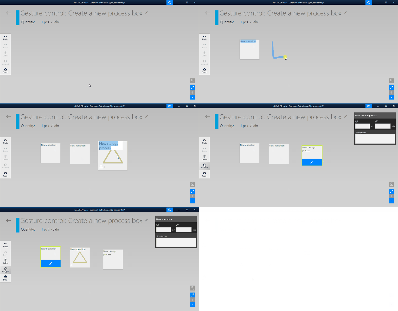
Creating a new process box:
Draw a closed-form element in a free area. The process box is created in this place and only embedded in the chart after having been connected to a transport.
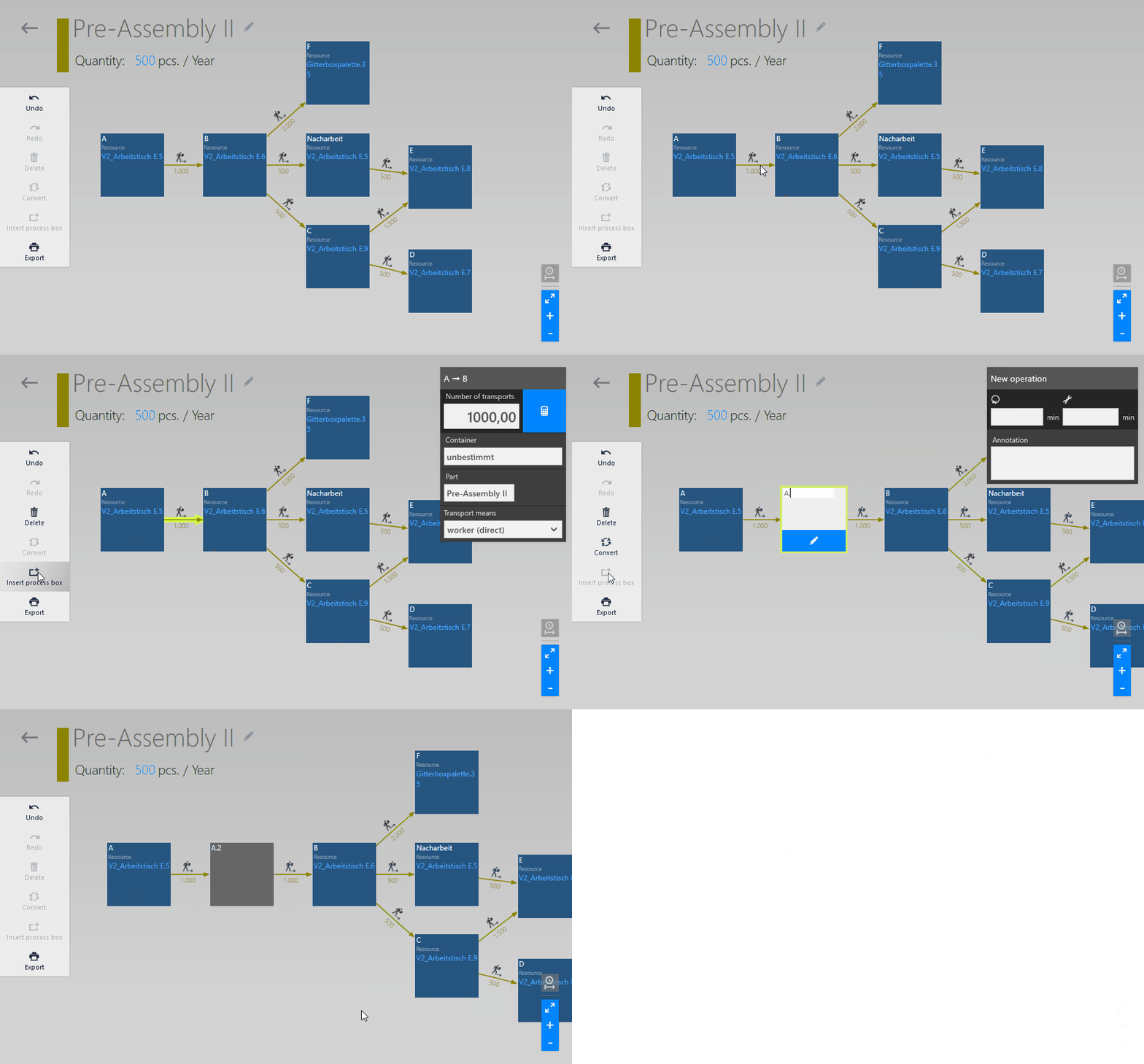
Insert a process box between two existing ones:
To insert a process box between two existing ones, select the transport that connects two process steps. Then click on theInsert process boxcommand in the menu.
Moving in the chart
It is neither necessary nor possible to move the process boxes or connection arrows for the transports. The methods above are a very good practice to describe the structure of the product flows.