Transport networks
Transport networks define the spatial course of route of Flow Relationships (e.g. transport routes or walking distances). They are used to specify the layout areas in which the material flow is permissible.
Transport networks comprise
- Nodes (visualized by way of solid colored circles) and
- Edges (arrows) running between two nodes.
It is thus possible to take any restrictions (roads, columns, gates, existing transport means, etc.) into account in the material flow study. The course of the material flow is subsequently determined in visTABLE®touch by way of these restrictions.
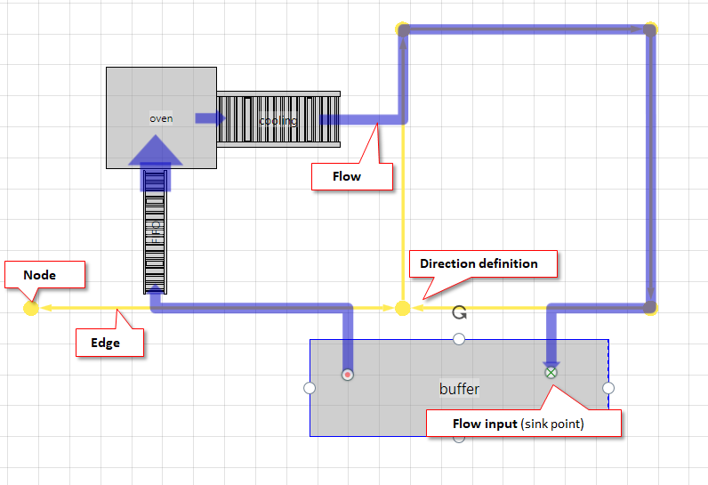
A transport network describes the possible movement areas
- either all means of transport (network
universal) - or only one type of transport equipment (all other nets, e.g.
forklift,truck,trolley).
Definition of means of transport
The means of transport types are defined in visTABLE®logix in the means of transport overview. A means of transport type stands for a set of similar means of transport. For example, the type handcart will be used for all handheld means of transport with comparable capacity and cost structure. visTABLE®touch provides a transport network of the same name for each net-compatible means of transport type listed there.
Finding routes in transport networks
As a rule, each individual flow in the layout area (2D) is a direct connection between source and sink (arrow in the direction of the sink). A flow will find, however, the shortest route (permitted by the specified direction) (Flow Length) by way of the part of the Transport Network that may use the corresponding Type of Transport Means if this transport network has at least one edge. The following rules apply:
- The system always searches for the shortest connection from the material flow output of the source to the nearest network edge that can be used (network entry point).
- The system searches for the shortest way from the material flow input of the sink to the nearest network edge that can be used (network exit point).
- The system searches for the shortest path in the network between network entry and exit points. A valid path is found if network entry and exit points are connected to each other via edges. In this context, the directional character of the edges from the source to the sink (unidirectional/bidirectional) is decisive.
- In case of failure of one of the steps 1 - 3, a direct connection results between the material flow output of the source and the material flow input of the sink (dotted line in pink).
Creating a new transport network
Before a transport network can be extended or refined by adding and moving nodes, first an edge must be added to the layout. To add a new transport network to the layout, proceed as follows.
Procedure
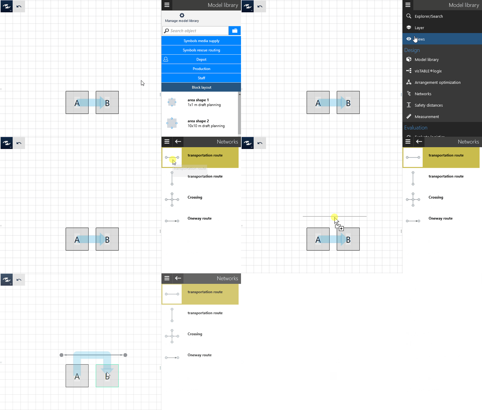
- Switch to the task area
Design>Transport Networks. - Position a transport route, junction or one-way road in the layout by using the drag and drop method. You have created a new transport network of the
Universaltype. The material flow is calculated automatically, taking into account the newly added transport network.
Practical tip: Editing transport networks
Transport networks can be edited in the layout area, similarly to other objects: The operations “Select”, “Delete”, “Move”, etc. will then only be available if the visibility of transport networks is activated. A description of how to specify the visibility of transport networks can be found in the Layer Task Area. The flows are calculated independently of the visibility of the transport networks. If you create a new transport network by using the drag-and-drop method, old transport networks become visible automatically.
Adding nodes
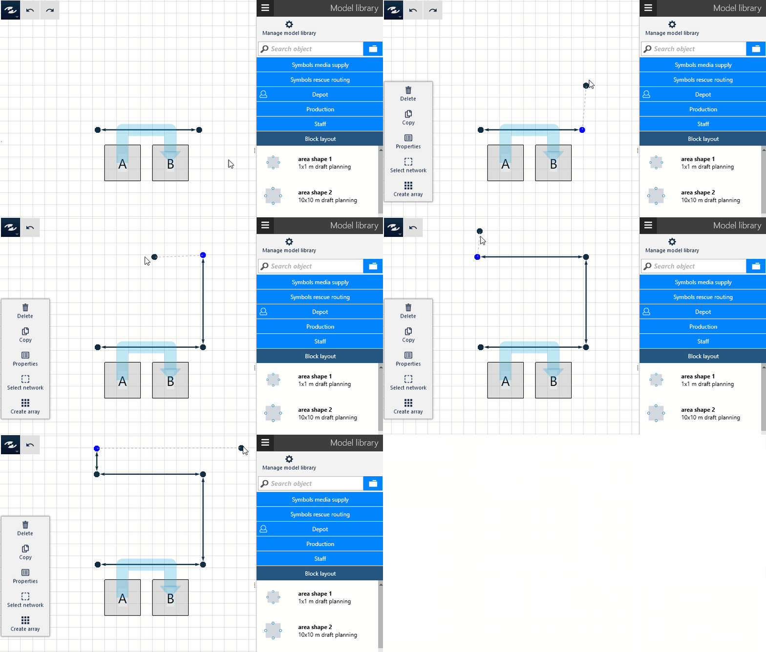
Transport networks can also be extended by adding nodes.
Procedure
- Select a node. A
+symbol is displayed in the vicinity of the node. - Click on this
+symbol. A new node is created and is suspended on your mouse. - Move the mouse to the point at which you wish to place the node.
- Click again. The node is placed at the position of the mouse, and an edge is created which connects the node selected in step 1 with the new node.
Dividing edges
It is possible to divide an edge in the middle, resulting in a new node at this point. The new node can be used e.g. as a junction or moved as desired.
Procedure
- Select an edge. The
Dividecommand is displayed in the dynamic menu. This command is not displayed if more than one edge is selected. - Click on the
Dividebutton in the dynamic menu. A new node is created in the middle of the selected edge. This node is selected automatically. Now the newly created node is in the selection. You can immediately continue with building up the network with this node.
Deleting notes and edges
Nodes and edges can also be deleted, similarly to other layout objects. The deletion of a node can result in deletion of edges connected to the node, or nodes connected to each other by way of other edges can be connected to each other by creating a new edge.
Procedure
- Select an edge or a node. The
Deletecommand is displayed in the dynamic menu. - Click on
Delete. The selected objects are removed and the network is completed automatically.
Assigning a type of transport means
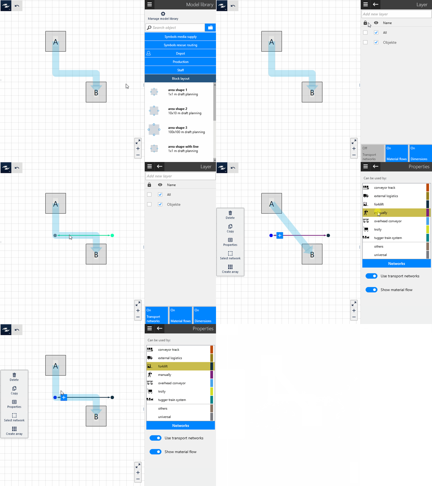
Transport networks created by way of drag and drop is assigned the type of transport means Universal and can therefore not be used as a restriction for flows. If you wish to assign your own transport networks a specific type of transport means (e.g. Forklift or Hand truck), the transport network must be assigned the appropriate type of transport means. The types of transport means are represented in the layout by way of different colors of the nodes and edges. The colors cannot be changed; they are assigned by visTABLE®touch automatically. A network of the type of transport means Forklift, for example, can always be identified as such by black nodes and edges.
Procedure
- Make sure that the transport networks are visible.
- Switch to the
Layertask area. - Check that the visibility of
Transport Networksis set toON. - Select a node or edge.
- Click on
Propertiesin the dynamic menu; a choice of the types of transport means which are available for assignment is displayed. The type of transport means currently assigned is highlighted. - Select the type of transport means you wish to be assigned to the transport network. The material flows are calculated immediately, without taking into account your assignment.
Notes
- There are a few special types of transport means for which no transport network can be created. These types of transport means are characterized by the feature that each transport is realized by way of a direct relationship. This pertains to the following types of transport means:
- Gantry cranes, and
- Workers (direct).
- Gantry cranes, and
- Each transport network (and thus each node and each edge) can only be assigned one type of transport means.
- Connected nodes and edges is always assigned the same type of transport means. If the type of transport means is changed for an individual component, the nodes and edges are assigned for all components connected by way of them.
Joining / creating branches and junctions
Transport networks are often only roughly defined by way of nodes and edges. In the further course of planning, however, it can become necessary to produce branches on edges or create junctions. Instead of rebuilding the transport network from scratch, it can also be refined directly. When moving nodes, visTABLE®touch recognizes whether they coincide with another node or edge and then automatically creates a branch or junction.
To connect two edges with each other by way of a branch, proceed as follows.
Prerequisites
Only nodes and edges of networks which is assigned the same type of transport means can be connected with each other. It is not possible to use the described procedure to generate transfer points between networks with different types of transport means. To this end, a resource and appropriate logistic processes are provided which must be described by way of visTABLE®logix.
Procedure
- Select an edge.
- In the dynamic menu, run the
Dividecommand. A node is created in the middle of the edge and selected automatically. - Click on the
+sign in the vicinity of the newly created node. A new node is created and suspended on the mouse until you have specified its final position. - Click initially in any place to create the node in this place.
- Then drag the new node to a position on the other edge to create a branch. A branch is created at the selected position on the edge; subsequently, it is connected to the node created in step 3.
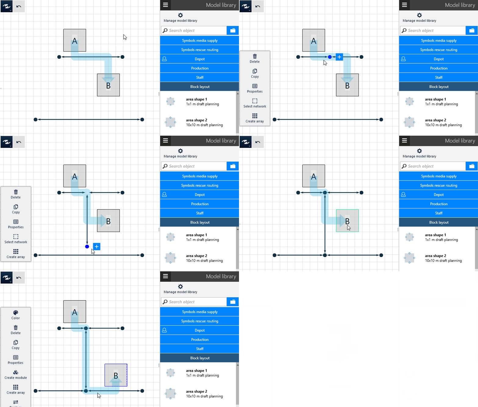
Specifying the direction
Transport edges must always be assigned a certain direction. Furthermore, the permissible direction of the material flow must be specified. Thus, one-way traffic can be realized. An arrow that visualizes the direction can be found on the ends of an edge.
To change the direction of an edge, proceed as follows.
Procedure
- Select an edge.
- In the dynamic menu, run the
Directioncommand. Click to change the direction of the edge. The currently set direction can be recognized on the ends of the edge.
Selecting a network
It might be necessary to move complete areas of a layout in their entirety, including all transport networks of the appropriate subarea, to another position within the layout. Use the multiple selection function to draw up a selection rectangle. If, however, not all components of a transport network are included in the selection, it is not necessary to draw up the rectangle anew. The Select Network command can be used to add all components of a network to the selection which are connected with a component that is already included in the selection.
Procedure
- Select at least one node or one edge or several transport networks.
- In the dynamic menu, select the
Select Networkcommand. Subsequently, the selection will also include the nodes and edges that are connected with the currently selected networks by way of nodes and edges.