Basic tutorial 3: From the ideal layout to the real layout
This tutorial is intended for new users. It teaches basic steps for layout transformation from the ideal layout created in our second basic tutorial to the real layout.
Introduction
To convert an ideal layout into a real layout, so-called restrictions have to be considered. These usually result in additional space requirements or restrict the degree of freedom in the design of the areas. Here you will learn three things that always have to be considered:
- Restrictions imposed by the building structure,
- Transportation routes,
- Safety distances.
Step 1: Insert floor plan (import a CAD drawing)
We need at least the floor plan of the building. Typically, these are provided by the facility management or architectural office as two-dimensional CAD drawings in DWG or DXF format. Such drawings are integrated into the visTABLE® layout as so-called background CAD using the Import function in the System menu.
The following video illustrates how to import a CAD floorplan:
Proceed as follows to import the floorplan:
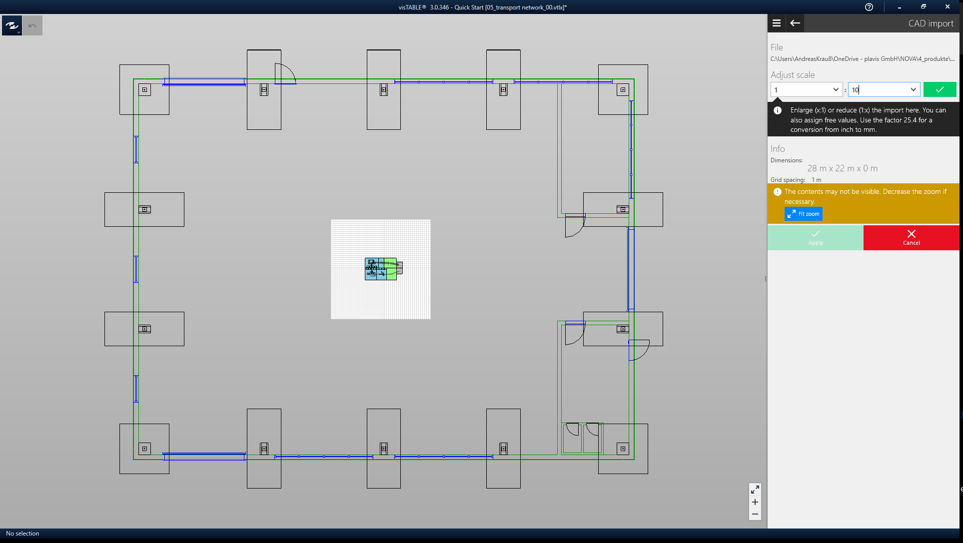
- Import the file
QuickStart building CAD.dwg - Scale the floor plan to a scale of 1:10 and tap the green check mark (see image below).
- Finally, tap Apply.
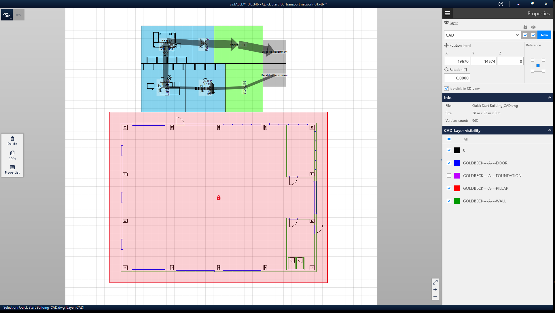
After importing, the floor plan can be moved. Editing actions are available via the dynamic menu. The internal layer structure of the CAD drawing can be accessed under Properties. Hide CAD layers that are not helpful, such as the foundations.
Step 2: Create the areas for transportation
There are two aspects to consider for the transport route:
- How wide does the transport route have to be?
- Which transports should it accommodate in which direction (i.e. which material flow runs over it)?
Both aspects are modeled separately in visTABLE®. The easiest way to model the width and other geometric parameters is to use the already known block layout objects. Differentiate transport routes and the other block layout objects by using your own layer:
- Assign the layer
block layoutto all (resource) blocks. - For the block layout objects of the traffic routes define a layer
routes.
The following video illustrates how to work with layers:
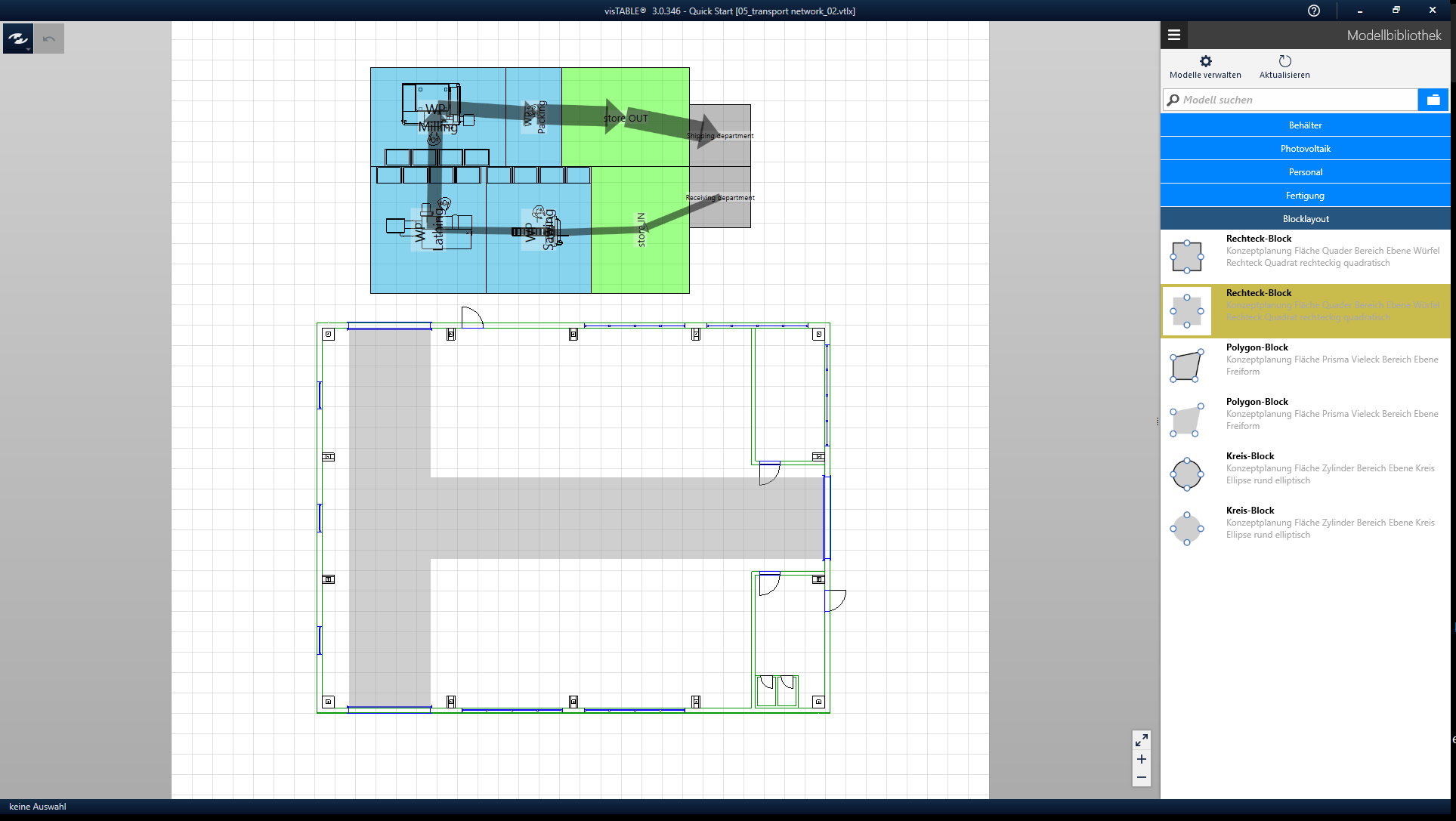
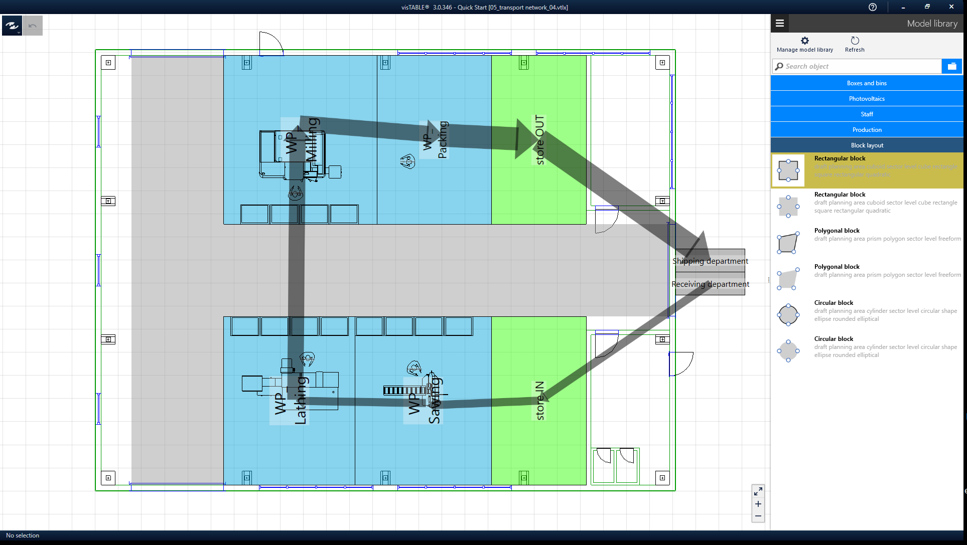
Start designing the area requirements of the transport routes by adding transport routes to the ideal layout created in our second basic tutorial. Use the model Areas without line from the catalog Block layout with the following properties:
Label: Path- Hide designation
Layer: RoutesType of area: TransportWidth [mm]: 4000Length: Results from the layoutColor: Gray
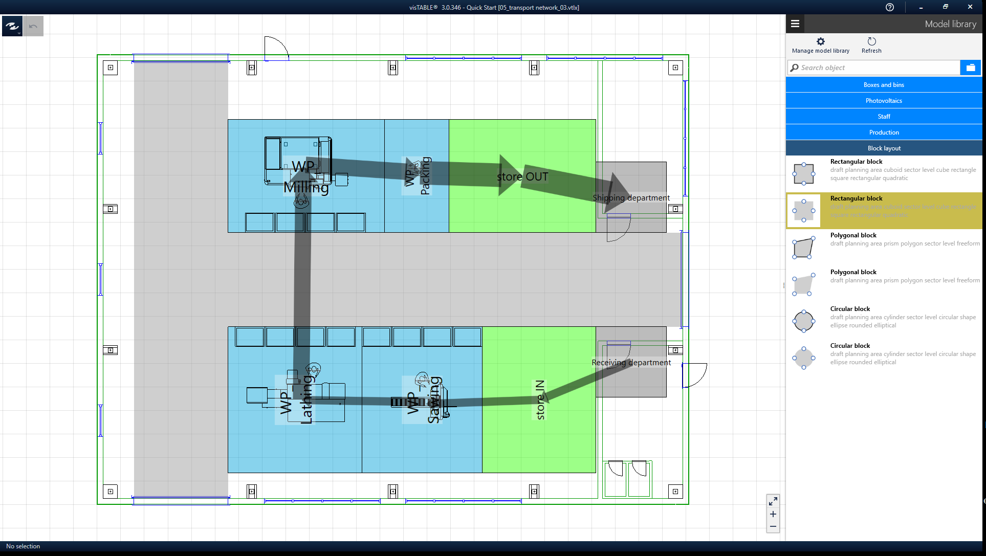
Now move the block layout areas so that the transport areas run as shown in the picture. Do you remember the snapping and alignment functions in the first basic tutorial? This will help you when lining up the block layout and transportation areas.
Now it is easy to fit the blocks in.
Step 3: Check area dimensioning
In the meantime, colleagues from divisional planning have worked with production staff to determine what additional operating equipment is required at the work places. The space required for this equipment necessitates the expansion of the block layout areas:
- WP Sawing: min. 41 m²
- WP Lathing: min. 43 m²
- WP Milling: min. 48 m²
- WP Packing: min. 36 m²
- Stores: 30 m² (unchanged)
Now it is necessary to examine the extent to which the areas fit into the building without having to question the optimization of the layout and the transport route widths.
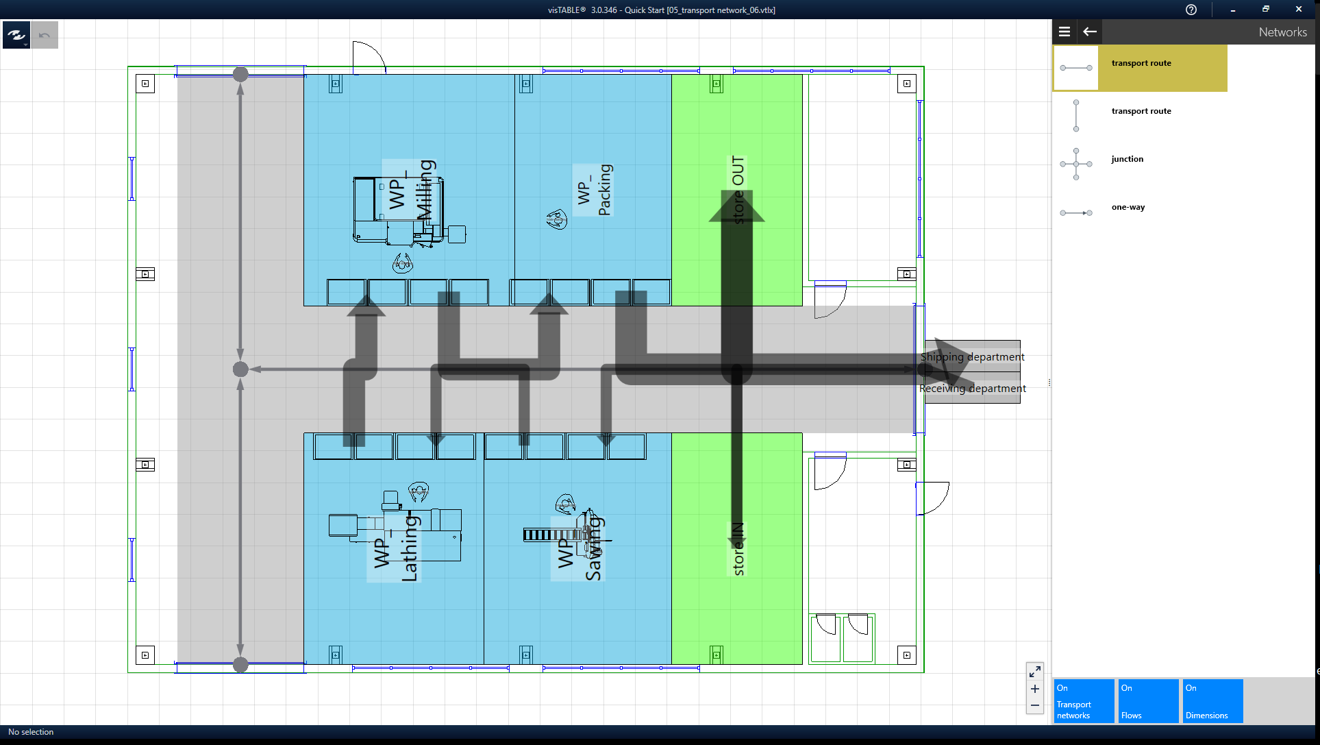
Step 4: Material flow mapping
For the material flow mapping use transport networks. How to do this for the example layout is shown in the following video:
Step 5: Check safety distances
Finally, we want to place the peripheral objects.
WP Sawing:
- 1x
cantilever rack single sided - 2x
mesh box pallet 1200x800x400mm - 1x
workbench with top shelf - 1x
workshop cabinet 1200mm
WP Lathing:
- 4x
mesh box pallet 1200x800x400mm - 1x
workbench with top shelf - 1x
workshop cabinet 1200mm - 1x
swarf tray 3 wheels
WP Milling:
- 4x
mesh box pallet 1200x800x400mm - 1x
workbench with top shelf - 1x
workshop cabinet 1200mm - 2x
swarf tray 4 wheels
WP Packing:
- 4x
mesh box pallet 1200x800x400mm - 2x
workbench - 1x
workshop cabinet 1200mm
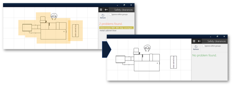
Now it is a matter of safeguarding the minimum distances between arrangement objects. The function safety distances can support this:
The picture shows how it works in our example:
Planning-tip:
The visTABLE® standard models have fixed defined functional spaces around their outer contour. If you want to define your own functional spaces, model them using objects from the Block Layout catalog. Place them on their own layer if you want the functional spaces to be hidden. Group them with the resources to easily move and rotate them together.
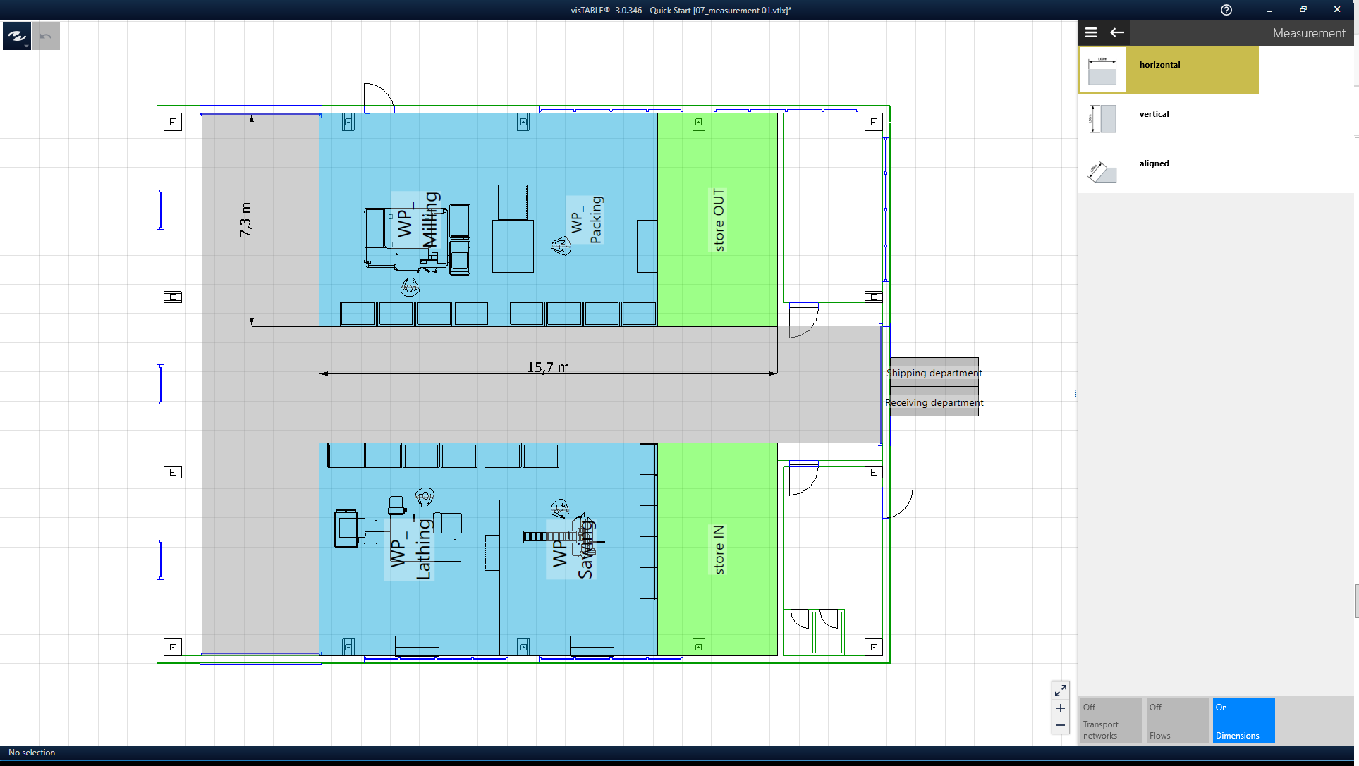
Step 6: Create dimensions
Dimensions are used to identify important functional dimensions in the layout. Use them when such dimensions are to be communicated, for example, in PDF prints of the layout. In the video you can see how to create dimensions for the sample layout.
Result of the tutorial
Now you have done all the basic steps for layout creation in visTABLE®. But to realize real planning projects, it is not enough to simply apply the steps shown here to an entire factory. This would lead to complexity problems.
However, the procedure shown in the three basic tutorials is directly transferable for self-contained production areas from 200 m² to approx. 5,000 m². For smaller and larger areas, layouts should be broken down further or aggregated hierarchically. You can find tips on this in the blog posts, among others, which are compiled for you in the last chapter of this tutorial.
Further resources
- Methodical support in designing the layout
- What you should definitely know about Factory Planning (visTABLE®Blog)
- How to organize factory layout planning? (visTABLE®Blog)
- Job shop production vs. production line? (visTABLE®Blog)