Properties
User interface
The object properties are displayed in the Task and Tool Area; it is divided into sections of which some can be hidden. Which sections are displayed depends on the selection in the Layout Area. Special points to be observed are explained below together with the relevant object types.
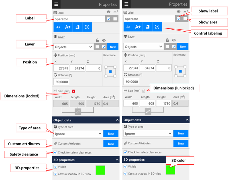
Label
Use this menu item to perform the following labeling tasks in respect of the objects:
- Labeling
- Visibility of the object name
- Visibility of the contents of the area (bounding box area)
- Font size control
- Font alignment control
 +
+
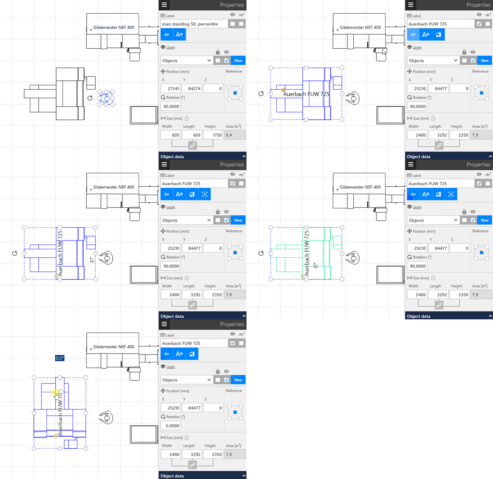
The label is automatically aligned horizontally or vertically based on the longest axis of the bouunding box of the selected object (legibility from left to right or from bottom to top; the position of the label can be changed interactively using the yellow Move label adorner).
- The alignment is fixed by clicking the
Change text direction button. It is possible to fix the text in a vertical or horizontal direction. Fixed labels retain their orientation regardless of the rotation of the associated object. - The alignment can be reset by clicking the
Reset text alignmentbutton.
Layer
Use this menu to perform the following tasks in respect of the layer on which the appropriate objects lie:
- Assignment to a new layer
- Assignment to an existing layer
- Locking of the assigned layer
- Hiding/showing of the assigned layer
Position
Use this menu to perform the following tasks in respect of the positions of the selected objects:
- Positioning in the x, y or z direction
- Rotation around the z axis
- Selection with reference to the point to which the position values are to refer (
Zero point)
Dimensions
Complete the following tasks for scaling a selected object here:
- Resize in each dimension individually or proportionally (control via link icon below input fields).
- Entering a fixed area content for block layout areas (control via lock symbol below area content).
- Lock scaling (control via lock behind the section title Dimensions).
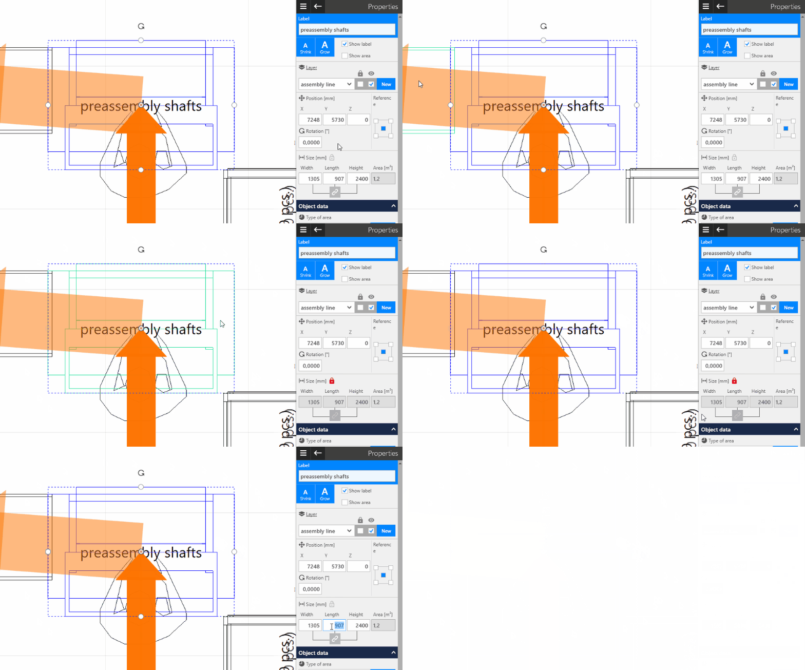
The link symbol beneath the input fields for width, length and height is used to control whether or not the respectively other dimensions are to be adapted at the same ratio when specifying the dimensions. The state of that symbol has no influence on the interactive scaling in the Layout Area.
The small lock is used to protect equipment from accidental changes of dimensions. This applies to both value entries and interactive scaling.
Area type
Specifies the area type of the selected objects for the Area Balance. It is also possible to create a new area type.
User-defined attributes
This menu item can be used to specify user-defined properties for the selected objects. A property consists of a:
- Name,
- Unit and
- Value.
Checking the safety clearances
Specifies whether or not the selected objects are also to be included in the Check of the Safety Clearances.
3D properties
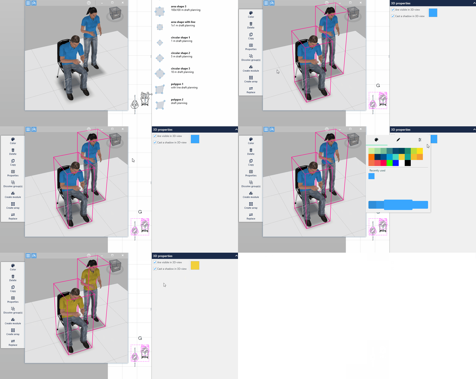
Specifies how the selected objects are represented in the 3D View.
- The
Transparencysetting is only available for block layout objects. - The
Shadingsetting is not available for block layout objects. - For colorable models, the
3D colorcan be specified here, e.g. the color of the workers shirts.
Object-type dependent properties
Groups / several objects
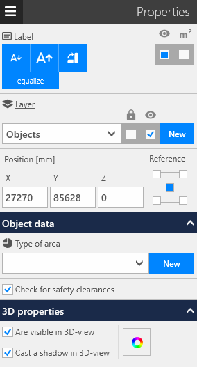
- The position specifications refer to the BoundingBox of the complete selection.
- Changes to object properties always affect all objects in the selection for which these properties are available. This applies regardless of the visibility of the objects in the selection.
Block layout object
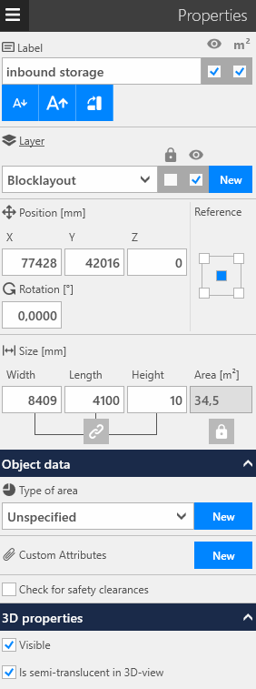
- The contents of
Areacan be locked by way of the lock symbol beneath the input field for the area contents. As a result, the respectively other dimension in the plane (i.e. the length or width) is adapted by interactive scaling in the Layout Area or when specifying dimensions such that the area contents do not change. - It is not possible to specify length and width for
Polygons.
Configurable objects
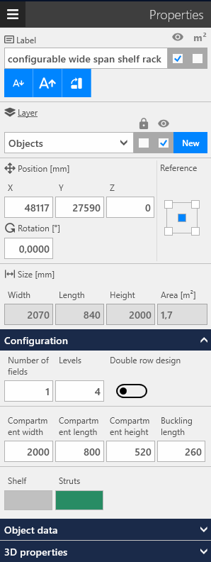
For configurable objects, the geometry and/or 3D coloring is not adjusted by interactively scaling or entering the overall dimensions. Instead, a Configuration expander is displayed. The corresponding parameters can be set for each configurable object here.
CAD background image
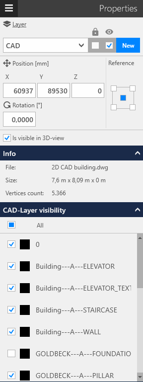
- Use the
Visible in 3Doption to specify the visibility in the 3D View. - The name of the imported file, the size and the number of elements contained therein are specified in the
About...area. - The visibility of the layers contained in the imported file can be changed in the
Layer Visibilityarea.
Text box
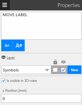
- The text can be modified in the upper area. It can comprise several lines (use
ENTERfor line break). - The position of the height of the text in the 3D View can be controlled in the
z positionarea.
Transport network
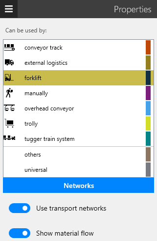
The Type of Transport Means is assigned in the list. Use the Transport Networks button to navigate to the model library to be able to insert new network components. The switches control whether
- the material flows should run along the networks (
Use transport networks), - the material flows are displayed at all (
Show material flow).
Dimensioning
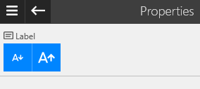
Merely the font size of the dimensioning can be changed.